This Design Idea shows a way to drive low-power electronic circuits using a single 1.5V cell. The design is based on a free-running oscillator that drives a flyback transformer to generate a controllable higher voltage. It can be used to power analog circuitry, microcontrollers, and any other light loads.
The power circuit was designed, simulated, and constructed. It was shown to operate reliably with a power draw of less than 50mW, even when the supply drops to 1.1V. The regulated outputs tested for the given circuit values were between 6V and 24V by the adjustment of a single resistor value. The output power is sufficient to drive a PIC microcontroller in low power mode (15µA@32kHz). With no modification, the circuit will work as a strobe, and flash a string of LEDs – or a power LED – at rates from 0.1Hz to 20Hz. It might seem a lot of circuitry for otherwise “simple” tasks, but it is worthwhile given the low supply voltage, and the fact that the output can be regulated or the flashing controlled.
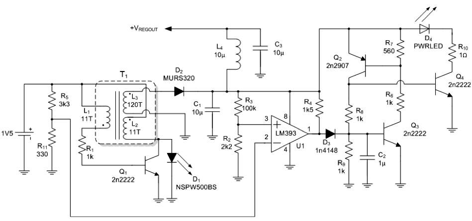
Figure 1 Circuit diagram of the 1.5V inverter. Inductors L1 and L2 (10 turns, 22 AWG), and L3 (130 turns 32 AWG) are wound on a Fair-Rite Products Corporation core part number 5961001801.
To use the circuit for a regulated output at +VREGOUT in Figure 1, for instance 20.7V in the following discussion, resistor R2 was set to 680Ω and R3 to 100kΩ. The voltage across R11 is set by the R5/R11 potential divider to about 140mV. The oscillator made up of Q1 runs continuously on application of power, and couples energy magnetically into L3 from L2. Once the voltage across C1 rises above 2V, comparator U1 is effectively powered. Initially, the voltage across R2 rises gradually as the capacitor charges up, until it just exceeds the voltage across R11. The connection is such that it will be compared constantly with the 140mV by the open-collector comparator U1. The thyristor comprised of Q2/Q3 are similarly unpowered and also untriggered by the output of U1. The capacitor continues to charge unhindered. Therefore, depending on the value of the R2-R3 combination, the output of U1 will go high when:
For more detail: Flyback switcher works down to 1.1V, flashes HBLEDs