
The objectives of this project were (1) to make an object float, by means of magnetic levitation and controlled by an Arduino Nano and (2) documenting the whole process allowing other people to build one on their own.
There were some requirements, too. First, I wanted an object of a certain size and weight, floating in a very stable way (no jitter, no oscillations,…). Additionally, safety was a concern (the main magnet has a 24 Volt and 25 Watts rating, producing quite some heat).
And last but not least: the end result had to be ‘nice’, earning its place in my living room !
I finally came up with an 11 cm (4.3″) magnetically levitated earth globe, not only floating but rotating at a fixed pace as well, illuminated by two digitally controlled led strips and nicely fitted inside a wooden lantern.
The movie below explains it better than a thousand words … check it out !
Supplies
This is a list of the most important components I used
- a wooden lantern (of course). Internal dimensions: 180 x 180 x 300 mm minimum
- wooden laths and planks
- spacers, nuts and bolts
- plexiglass 3 mm (you will have to cut it yourself)
- heatsink 1.85°C/W, 100 x 88 x 35mm
- electromagnet ITS-MS-7040-24VDC: this is a fairly strong electromagnet weighing 800 grams, and rated at 1200 Newton holding force, 24 V DC, 24 Watt
- 3D printed ‘globe rotation hall sensor assembly’ (link to STL file provided in this instructable)
- 3D printed spider to hold the six rotation coils (link to STL file provided in this instructable)
- Empty plastic spools to create coils
- Block Enamel-coated copper wire 0.28 mm
- Adafruit RGB ledstrip APA102 60 led 1 meter
- Honeywell hall effect position sensor SS495AAnalog Devices
- temperature sensor TMP36Neodymium magnet circular 10 mm height 5 mm
- Neodymium magnet cube 20 x 20 x 20 mm
- DC to DC (step down) convertor Velleman VMA404
- Arduino Nano R3PCB designed with Autodesk Fusion 360 (Schematic and Gerber files attached to this instructable)
- a lot of electrical components (PCB BOM attached to this instructable)
- Wall power supply 24 Volt 36 Watt DC plug 2.1 x 5.5x 11 mm
Software, tools and online services
- Autodesk Fusion 360: PCB design. Autodesk has a free version of their software, and it’s working great
- Seeed studio Fusion PCB manufacturing. You will need to upload the Gerber files (zip file attached) when placing your order. PCB will be delivered, ready for assembly.
- Highly recommended: oscilloscope, e.g. Tektronix TBS1052B
- 3D printer
- soldering station
- The usual tools like tweezers, pliers, multimeter …
Step 1: Understanding Magnetic Levitation
One way to achieve magnetic levitation is to position an electromagnet above an object—in this case, an earth globe—which contains a very strong magnet. By constantly measuring the vertical position of the object, we can vary the magnetic force exerted by the electromagnet on the object’s magnet to keep the object in place.
This happens much in the same way as driving a car on the highway. By constantly measuring whether the car drifts to the left or to the right, the driver can stay in his/her lane by applying small corrections only. This mechanism is called a “control system” or “feedback system.”
This magnetic levitation control system is not a “linear” system at all. For instance, the relationship between current applied to the electromagnet and force exerted (on the globe’s magnet) is quadratic. Moreover, this force varies with the distance between electromagnet and magnet—which seems logical. But this relationship also is quadratic! That means that the “parameters” (we’ll talk about that in a moment) used to keep the globe’s position stable are critical.
Any change to the globe’s weight, the magnet, the electromagnet or the position of the sensor will probably result in a highly unstable globe, and you will have a hard time finding the correct parameters (which will be trial and error, I’m afraid) to obtain stable operation again. Indeed, this non-linearity also makes it difficult to apply mathematical methods to calculate these parameters.
Step 2: Globe Lifting Control System: How Does It Work ?
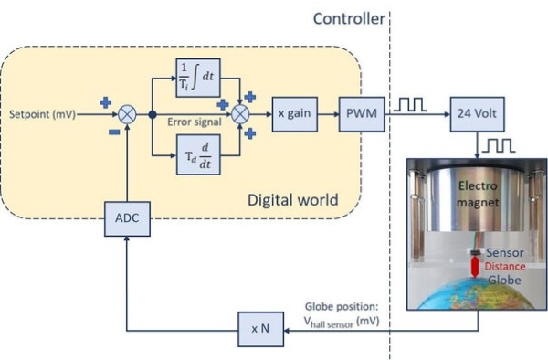
So, how does it work? Well, I’ll try to explain it in an easy way. And, in the meantime, please keep an eye on the figures. First, we need to determine the globe’s vertical position. This position is measured by a Hall effect sensor, a tiny device that measures the strength of the magnetic field (produced by the magnet mounted inside the globe), converting it to an electrical voltage. If the globe comes closer to the sensor, the magnetic field strength will increase and the output voltage will change. In our case, because of the way the magnet’s north and south poles and the Hall effect sensor are positioned, this voltage will decrease. Voltage will increase again if the globe moves further away from the sensor. So, the sensor effectively converts a position to a voltage!
This (small) voltage (typically between 100mV and 300mV at the operating point, depending on settings) is amplified before it is converted to a 10-bit number by the Arduino ADC (analog-to-digital converter). Welcome to the digital world! This amplification is a necessary step, considering the very small voltage variations to be captured (less than a millivolt at the Hall detector output) and the 10-bit Arduino ADC resolution. Note that, from a control systems perspective, the ADC conversion can be considered a second “amplification” step. The ADC scales an input voltage to a number from 0 to 1,023. It is perfectly fine to consider this number as the digital representation of a (scaled) voltage. Or you can use “ADC steps” as a unit. Doesn’t matter, as long as you are consistent.
As a next step, the program will subtract this number (representing a position but expressed in millivolts—or ADC steps if you prefer) from the desired position (called “setpoint”), which should also be expressed in millivolts—or ADC units—and appropriately scaled. We can only subtract values expressed in same units. The subtraction gives us the deviation from the desired globe position. We call it “error signal,” because it is zero when there is no deviation. This deviation is (again) expressed in millivolts.
Forgetting for a while about the “integrator” and “differentiator” boxes in the figure (I’ll come to that in a moment), we have a third amplification step that is performed digitally this time. The amplification factor (“gain”) is stored as a constant in the Arduino program. Note that the total gain delivered by these three amplification steps is simply the product of the three individual gains. Whether these steps happen in the analog or digital world is not relevant at all! And this total gain is important, because a higher gain makes that a same (small) controller input (here: deviation in position) produces a higher output (here: a pulse with a higher duty cycle—we’ll come to that).
Imagine if this total gain would be very small. Not a lot would happen, right? More in general, with the gain too low or too high, the system risks to become highly unstable, so we need to choose it carefully.
Anyway, the amplified error signal is then fed to 16-bit Arduino Nano Timer 1 to generate a pulse with a specific duty cycle (PWM—pulse width modulation). If it’s zero, then the duty cycle will be zero as well. If it’s 999, the duty cycle will be 100%. The pulse duration is fixed at exactly one millisecond. This can be seen in the oscilloscope screen capture in the figure. The pulse produced will determine the “ON” time of the electromagnet (using power transistor Q1—we’re back in the analog world now) within that single millisecond. This will increase or decrease the “average” force exerted by the electromagnet on the globe’s magnet within that millisecond and as a result the globe’s position will change.
As you might have guessed, this whole process is repeated every millisecond (interrupt driven). Every cycle is started by reading the ADC output to obtain the hall sensor voltage. If the globe is in a stable, floating position, this voltage will be close to the setpoint voltage (in this example: around 1000 millivolts, which is 10 times the hall-effect sensor output). As with any control system, this voltage will fluctuate a little: if it wouldn’t, we wouldn’t need a controller. Think about that!
Check out the oscilloscope screen capture (yellow channel) and verify that every millisecond the globe is falling to the ground for approximately 500 microseconds and then moving upwards again towards the electromagnet (‘up’ is actually ‘down’ on the oscilloscope and vice versa. Sorry for that).
And what about these integrator and differentiator boxes ? Well…
Differentiating the error signal with respect to time and adding this term to the error signal provides a faster reaction to quickly changing globe positions (the effect of this term will be smaller for slower changing globe positions). The differentiator time constant Τd (which is also a parameter in the Arduino program) controls the weight of this term. It is the most critical of all parameters: it must be carefully chosen to obtain stability !
And why do we integrate the error signal (with respect to time) ? Well, imagine the system is in rest and the actual globe position corresponds to the setpoint: this reduces the error signal to zero, as well as the PWM output (pulse with zero duty cycle) and the electromagnet’s force exerted on the globe. But this situation is impossible: because of the globe’s weight, it needs a counterforce. So, the globe’s position in rest will be a little lower than indicated by the setpoint (which leaves us with a non-zero error signal and, consequently, a non-zero PWM signal and a counterforce). This is called ‘static error’. Now, if we integrate the remaining error signal, the controller (PWM) output will slowly increase, the globe position will approach the desired position, the error signal will become zero and integration will stop… exactly when the globe is where we want it to be. The integrator time constant Τi is, as you will have guessed, another parameter in the Arduino program. It is less critical than Τd.
Conclusion: 4 parameters are important here. Setpoint, gain, integration time constant and differentiation time constant. You’ll find these constants defined in the Arduino program.
And why is the sampling time 1 millisecond ? Why not 10 milliseconds ? In free fall, an object initially at rest will fall about 5 micrometers in 1 millisecond. In 10 milliseconds, this increases to 0.5 millimeter (x 100). Not exactly a stable situation as perceived by the human eye and probably a lot more difficult to keep the system stable from a control system perspective. That answers it !
Step 3: Electromagnet Assembly
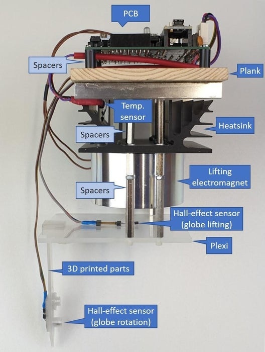
This assembly contains everything we need, except for the coils used for globe rotation and the led strips.
The electromagnet is quite powerful and produces a fair amount of heat. To keep everything safe, a quite large heatsink is placed on top of it. Additionally, a temperature sensor is fixed to the heatsink. It will be used to continuously control temperature.
Above the heatsink comes a wooden plank (used to ‘hang’ the assembly in the wooden lantern without the need for any nuts or bolts). Just underneath, notice an aluminum corner profile to keep the plank in position. Threaded spacers connect the plank with the base of the heatsink.
Underneath the heatsink, using the same holes (which you will have to drill, of course) we have another set of threaded spacers arriving at a plexiglass plate, holding the sensor we use for vertical position measuring (hall-effect sensor).
The plexiglass measures 90 x 105 mm. The back edge extends 67 mm from the hall-effect sensor (electromagnet center) position. Note that this last dimension is important as this is where the 3D assembly holding the globe rotation hall-effect sensor will be attached to the plexiglass. We’ll discuss this later.
Also, you will have to cut the plexiglass plate and drill holes in it. Carefully measuring and making a few sketches first, will prove to be a big help !
Important: make sure that the spacers (and the bolts underneath the plexiglass) are not magnetic.
Step 4: Lifting Hall-effect Sensor
Several ways exist to accurately measure the distance between globe and electromagnet – more correctly, to measure the deviation between desired position (‘set point’) and actual position. A common method is to use a light source at one side of the globe and a light detector at the other side. But in our case, as said, we use a hall-effect sensor measuring the strength of a magnetic field (which depends on the globe position) and converting this to an electrical voltage.
Actually, this sensor will not control the position of the globe with reference to the electromagnet, but with reference to the sensor itself. But because this sensor is fixed in position, this will ultimately determine the setpoint: the position of the globe with reference to the electromagnet.
As said before, the vertical distance between electromagnet and sensor (or plexiglass plate) is critical.
With the electromagnet I used (height 40 mm), the plexiglass plate is 58 mm away from the heatsink (which can be obtained by stacking 15 mm and 40 mm threaded spacers, adding a nut in the middle). This gives a ‘gap’ of 18 mm between electromagnet and hall sensor.
A question you might ask: doesn’t the magnetic field of the electromagnet influence the sensor reading ? Well, yes… but this is not a problem, because while we read out the sensor value (every millisecond), the electromagnet is always in the same (‘ON’) condition (you can verify this by looking at the scope screenshot, above). So, it’s attribution is constant and can be discarded.
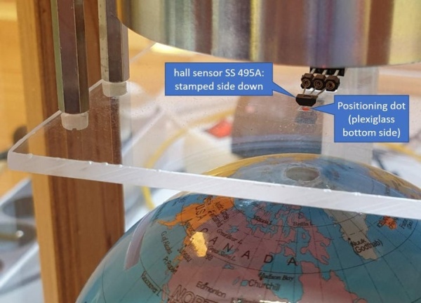
This hall-effect sensor needs to be placed exactly beneath the center point of the magnet. If not, you will introduce oscillations in the system and your globe will start to ‘swing’ in a horizontal direction, which is something the electromagnet cannot control. You will have to figure out how to determine that position. When doing it visually, take into account a thing called ‘parallax’. Suggestion: once you have determined that spot, put a small dot on the bottom side of the plexiglass. This will then help you position the hall sensor.
The hall-effect sensor is placed into a receptacle with precision contacts, glued to the plexiglass plate (I used Loctite superglue). This allows for easy fine tuning the sensor position because the sensor leads are not soldered. Assuming we’re using an SS 495A sensor, the stamped side must be facing down (the Arduino program assumes it).
When gluing the receptacle, make sure the plexiglass plate is clean and dry. We’ll deal with the PCB connection later.
Step 5: Temperature Sensor

The temperature sensor continuously measures the heatsink temperature: when it passes a set threshold, magnet and coils will be shut off.
You will need to mount the sensor in such a way that it makes good mechanical contact with the heatsink. How to do that will largely depend on the heatsink used.
We’ll deal with the PCB connection later.
Step 6: The Globe
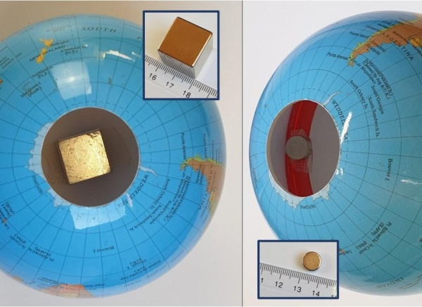
I was able to find a globe for use as piggy bank. This has the advantage that there’s a big opening at the bottom (and the disadvantage there’s a slot for throwing in money, too). In this case we’ll use this opening to position a strong permanent magnet (Neodymium, 20 x 20 x 20 mm) inside, near the globe’s geographic North Pole. I used double-sided adhesive tape to do the trick. You’ll need some chirurgical skills and good thinking to finish the job without having to open (and possibly damage) the globe, but… it’s possible.
Make sure you position the magnet with its north pole facing upwards (a cube has six sides, so you will have to do some experimenting). Be careful not to make a mistake here: if you place the magnet upside down, you will not be able to make it work! Best is to use a compass to determine the magnet’s north pole: a magnet’s north pole attracts a compass needle’s south pole: this is the needle pointing in the direction of the earth’s geographic South (this looks strange, but the earth’s magnetic North is located close to the earth’s geographical South and vice versa).
Later on, you will have to reverse the electromagnet wires if the force exerted on the globe’s magnet proves to be repelling instead of attracting. But don’t worry about that for now.
But we also want the globe to rotate, right ? This will require placement of two additional (smaller) magnets inside the globe. Also these are of the Neodymium type. And again, I was lucky… the globe I use, is made of two plastic halves with an inside border (in red) used to glue them together (I guess). This border is the ideal place to position these two magnets: one at the Greenwich meridian, and the other… at the opposite side, of course (the anti-meridian). Note that I used double-sided adhesive tape.
Important: position the magnet at the Greenwich meridian with its north pole facing up, the other one with its north pole facing down. The magnets will generate a (very small) torque, keeping the globe rotating – but that comes later.
Step 7: Globe Rotation Coils
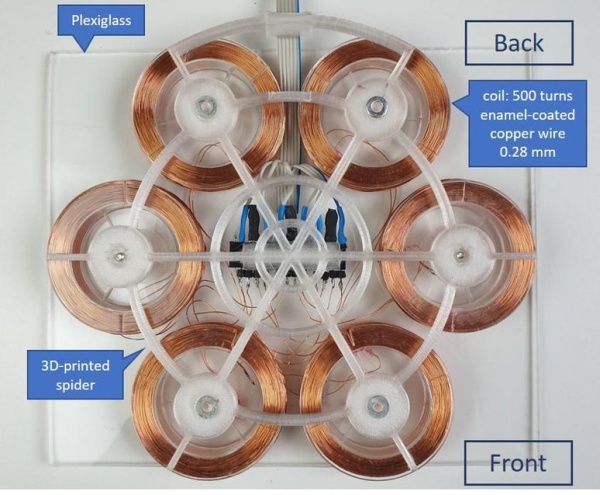
To create a globe rotation torque, we need a rotating magnetic field. The six coils placed below the globe will serve that purpose.
You will have to make these coils yourself, out of empty spools (I found these on the internet) and 500 turns of enamel-coated copper wire (0.28 mm diameter). Supposing the coils you use will be similar to mine, this will produce a coil resistance around 20 Ohm, which is just fine.
The coils are held in place by a 3D-printed spider with six knobs, providing a tight fit with the center holes in the spools. The spider itself is fixed to a plexiglass plate by two screws.
The spider STL file (needed for 3D printing one yourself) is available for 3D viewing and downloading through this link: Sketchfab spider 3D model (you will need to create a free account first).
A two-pin header is soldered to each coil, these headers are all connected to a larger 15-pin receptacle (with 3 unused pins) glued to the spider, right in the middle.
The coils are numbered from 1 to 6 (check out pictures) and coil terminals are labeled A and B.
If, looking down at a coil from the top, the winding direction (from first to last turn) is clockwise, we define terminal A as the start of the first turn of the copper winding (close to the center of the spool) and terminal B as the end of the last turn of the copper winding.
If the winding direction is counterclockwise, then we designate the start of the first turn as terminal B and the end of the last turn as terminal A.
The coils will work together in 3 pairs: coil 1 and 4, 2 and 5, 3 and 6. Therefore, we will connect the 2-pin headers (coil terminals) to the receptacle (as shown in the pictures). As you can see, the coils ‘B’ terminals are simply interconnected for each coil pair. The Receptacle pins for the coils ‘A’ terminals are soldered to the flat cable (6 wires).
At the other end of the flat cable, we will solder a receptacle later. Foresee ample cable length for the time being.
The plexiglass plate, of course, will have to be cut to the desired dimensions, depending on the lantern you use.
If everything is correctly connected, at any given moment the vertical magnetic field orientation of three adjacent coils will be opposite to the magnetic field of the other three coils. At regular intervals, this field will rotate by 60 degrees, counterclockwise (looking at the coils from the top). This will create a torque on the globe’s two side magnets. Moreover, this rotation will be in phase with what the Arduino program expects. So, it’s very important to follow the connection instructions carefully.
To obtain a nicer visual effect, the coils are positioned some 130 cm under the two globe rotation magnets. As we don’t need much torque, even with this distance we will be able to keep the globe rotating.
Source: Floating and Spinning Earth Globe