Introduction / Why this project
In 2016 I build my first fish feeder, see Fish Feeder 1. The feeder worked fine for more then half a year. After that period the servos were worn out, causing the program to halt, without sending an error-mail. Oops.
I didn’t had the time to correct this fault, because the aquarium was replaced by a slighter bigger version (Juwel Rio 125). Although the Fish Feeder 1 could be reused I choose to build another / different Fish Feeder.
Design goals Fish Feeder 2:
- No buttons on the Fish Feeder.
- Connection to the Raspberry Pi. The Raspberry Pi controls the E-mail, time-tables, feeding results and a display.
- The Fish Feeder should flush fit the existing feeding slot in the Juwel aquarium cover.
- The Fish Feeder should be watertight.
- The storage container with fish food for at least a month should be easily accessible.
- The Fish Feeder should drop small amounts of granulate fish food into the water.
- The amount of food should be adjustable and must be measured.
- No servos.
Note:
- This fish feeder is only suitable for granulate fish food, flakes will cause the knife valves to malfunction.
- Some parts need to be accurate and precise. I also had to throw away parts out of spec. Breathe in – Breathe out – And start over.
The build started at the beginning of 2017. It took quite a long time to test the key-components before I was satisfied with the results. Please read the following key-components / instructables which are incorporated in this instructable:
- Optical isolated single wire communication
- Transparant epoxy box casing
- Linear actuator stepper motor
- IR Photogate
Key parts
- Arduino nano
- Stepper motor diver
- Stepper motor
- Bearings
- Earphone socket and plug
- Epoxy
- 1, 1.5, 2mm plywood
Step 1: Woodwork
This machine is mainly build out of wooden parts. When prototyping I like to use wood, parts can be swapped out, dimensions can be changed, tolerances of 0.1mm are possible, holes can be added or filled. Attached is the model, you can make it out of wood or you can print it.
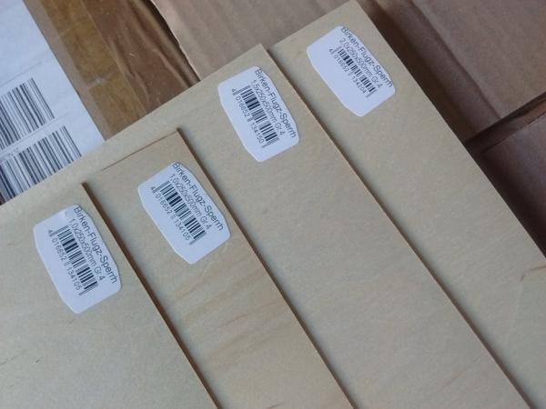
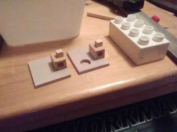
To test geometry of the wooden parts balsa wood is used. This material is too soft to be used in the Fish Feeder. Materials used:
- Birch plywood 500x250x1.0mm
- Birch plywood 500x250x1.5mm
- Birch plywood 500x250x2.0mm
- Birch plywood 500x250x3.0mm
- 18mm plywood
- 12x18mm mahogany
Step 2: Woodwork Casing
See model (01 Casing)
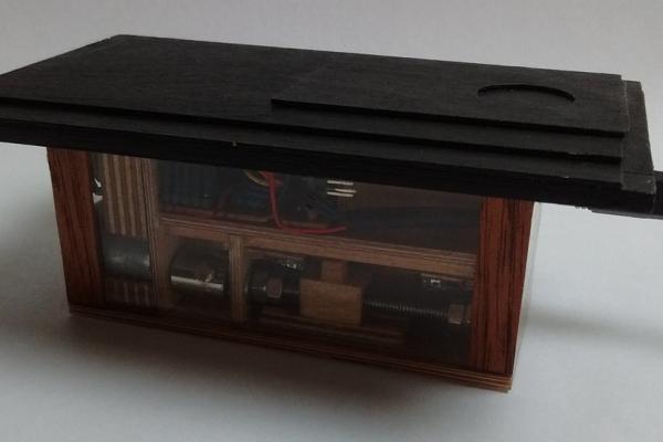
The casing houses the machinery of the Fish Feeder. It protects the machinery and electric parts to the moisture from the aquarium. The epoxy casing part fits into the standard Juwel aquarium feeding hole for the Juwel Easy Feed. The top of the Fish Feeder sits on top of the aquarium cover.
The choice for making the casing out of epoxy is because of:
- Epoxy is water-resistant.
- The internals can be visually inspected.
- The Fish Feeder cannot be seen when standing in front of the aquarium, only when lifting the covers.
To make the top of the casing less visible, I painted it black.
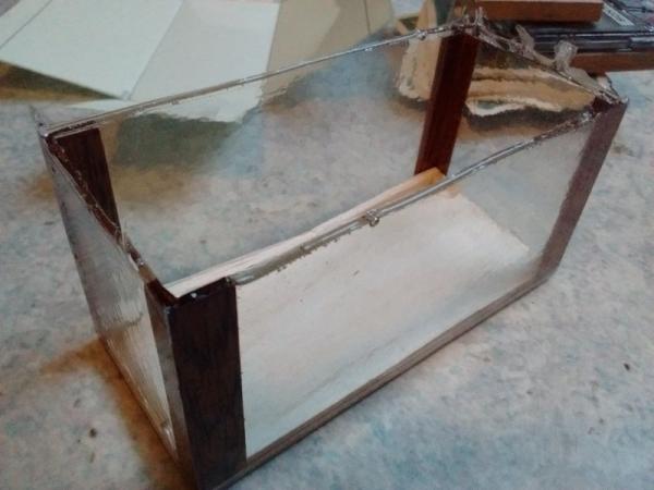
- Glue 4x L-profiles for the the transparent epoxy casing.
- The bottom part of the casing is the epoxy box casing (Transparant epoxy box casing).
- The bottom hole should be drilled after making the casing.
- The electric connector hole should be drilled after making the casing. (Not drawn, pending).
- Excess material of the epoxy casing must be removed and grinded to the desired height.
- Sand top of bottom casing. Between top and bottom a small gap is needed. Little pressure is needed to fit the parts.
- The top should be painted before epoxy glued to casing.
- Verify thickness of 2×2 and 10×2 with machine.
Step 3: Woodwork Cover & Hatch
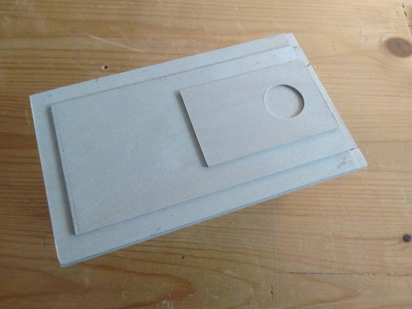
See model (02 Cover & 04 Hatch)
The cover slides into the casing top. The cover has a square hole. When slid into the casing top the machinery is covered, the silo is accessable. The hatch slides into the cover. When adding feed to the silo, only the small part has to be remove. To add grip to the cover, a hole is drilled in the top plate.
- Saw the parts to the desired dimensions.
- Glue the 2 assemblies.
- Fit the assemblies with the casing.
- Paint the assemblies.
Step 4: Woodwork Internals
See model (03 Internal)
The internal woodwork houses the silo for feed, linear actuator, knife valves, EL-board, switches and IR photogate. Ensure parts are accurate and right angled glued, unless otherwise specified. When finished and all parts mounted, this slides into the casing.
- Drill the parts with the bearing holes stacked to get a perfect alignment of holes.
- After applying epoxy the bearing holes are smaller. Drill holes again. Use some light pressure to press the bearings into position pressure.
- Manufacture the other wooden parts.
- Glue assembly led frame. Paint with epoxy. When inside the machine some areas are difficult to paint.
- After applying epoxy the holes are smaller. Check if the IR led and IR photodiode fit into the holes. If necessary drill the holes again.
- Paint internals and frame led as separate assemblies.
- Check dimensions with knife valves to ensure tight fit.
- 3.5mm is glued 2mm and 1.5mm sheet.
Step 5: Knifevalve
See model (05 Knifevalve)
Several options to submit food were considered, see first table:
- Rotating container with hatch valve. It is not easy to make this smaller.
- Screw (drill). The feeder is inside the aquarium, just above the water level. The food in the screw will be exposed to moisture. The food will stick to the screw, clogging the output.
- Knife valves (sliding)
How does the knife valve system work?
- Step 0: Normal position of valves. This is the normal position of the valves when the machine is inactive. The food container valve is closed. The aquarium valve is closed.
- Step 1: The food valve is moving to get a batch of food. Note that the food valve hole diameter is smaller. This is to be sure that the aquarium valve is capable to move the entire batch.
- Step 2: The food valve is loaded and is moving to the photogate.
- Step 3: The food is dropped through the photogate and is in the aquarium valve. The aquarium valve is moving to the outlet.
- Step 4: The food is dropped through the outlet into the water of the aquarium. The aquarium valve is moving back, closing the machine to moisture.
Step 6: Woodwork Knifevalve
See model (05 Knifevalve)
- Top knife valve has a hole diameter of 8mm, bottom knife valve has a hole diameter of 10mm.
- Check thickness, use a mold to epoxy the valve to the right thickness.
- At the right thickness, use Commandant M5 (scratch remover) to make the sliding faces silky smooth.
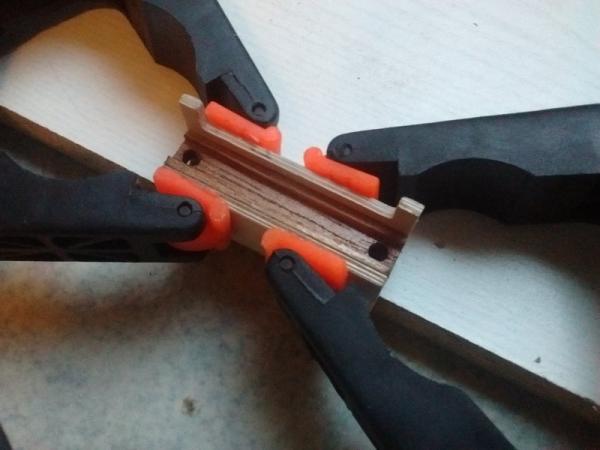
- The brass nut is glued in the square 10×10 L=15 block. The diameter is ~7mm. With the thread rod, brass nut and knife valves installed, glue the brass nut to the knife valve. Be careful not spill epoxy on the thread.
- When the brass nut is glued, fill up the gaps between nut and block with more epoxy.
Step 7: Woodwork Motor Clamp & Support
See model (06 Motor Clamp & Support)
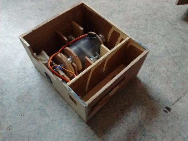
The motor clamp and support is used to position the stepper motors. When the stepper motor is clamped the axle is the only rotating part.
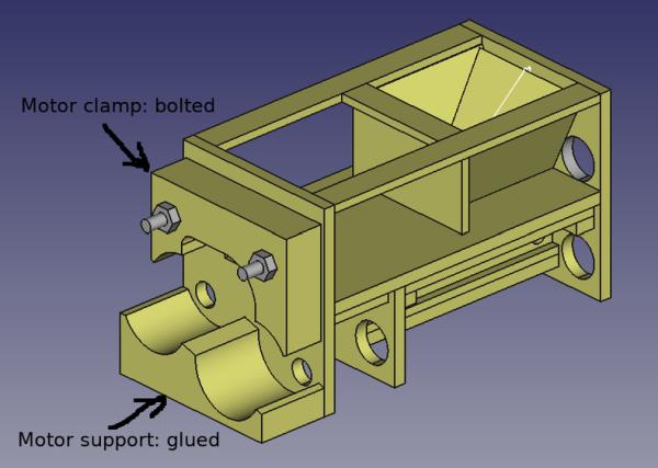
The motor support is used in the internal assembly and glued to the internals of the machine. Position the motor support with the stepper motors in position for a perfect fit.
The motor clamp is a loose part that is bolted to the internals of the machine.
To make sure the motor support and motor clamp are a perfect fit, these 2 parts should be made out of 1 piece 18mm plywood. To drill the holes, use a column drill machine. The holes should be perfectly perpendicular.
Manufacturing:
- Drill the large ø20 holes.
- Drill the smaller holes.
- Saw the outlines of the clamp and support.
- Thin the motor clamp to 10mm.
Source: Fish Feeder 2