Summary of First impression on the ESP8266 serial-to-WiFi module
The author reviews the ESP8266 Serial-to-WiFi module, highlighting its low cost, compact size, and ease of use for IoT projects. The article details pin connections, emphasizing the need for 3.3V power and level shifting when interfacing with 5V microcontrollers. It also explains how to upgrade firmware by pulling GPIO0 to ground during boot.
Parts used in the ESP8266 Serial-to-WiFi Module Project:
- ESP8266 module with 2x4 male pin headers
- PCB antenna
- Microcontroller (e.g., Arduino)
- LDO regulator
- Zener diode
- Resistors
- Perf-board
- Female 2x4 pin header
Continuing from my previous blog post about Hi-Link HLK-RM04 module, I have finally received the ESP8266 Serial-to-WiFi module that I’ve been waiting for. As I said previously, with the popularity of IoT devices, there is an increasing demand for low-cost and easy-to-use WiFi modules. ESP8266 is a new player in this field: it’s tiny (25mm x 15mm), with simple pin connections (standard 2×4 pin headers), and best of all, it’s extremely cheap, less than US$3 from Taobao.com!
What is Serial-to-WiFi? Simply put, it means using serial TX/RX to send and receive Ethernet buffers, and similarly, using serial commands to query and change configurations of the WiFi module. This is quite convenient as it only requires two wires (TX/RX) to communicate between a microcontroller and WiFi, but more importantly, it offloads WiFi-related tasks to the module, allowing the microcontroller code to be very light-weighted.
There are already a lot of excitements and resources you can find online about ESP8266. I’ve included a few links below:
- English Datasheets and Information (nurdspace.nl)
- Community Forum
- Hack A Day project
These are great resources to reference if you need help working with ESP8266. Below I document my own experience. I’ve also bought a few extra and put them available on the Rayshobby Shop for anyone who is interested in buying the module and don’t want to wait for the long shipping time from China ![]()
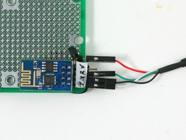
Pin Connections. ESP8266 is sold in several different versions. The one I received is the version with 2×4 male pin headers, and PCB antenna. In terms of the form factor, it looks a lot like the nRF24L01 2.4G RF transceiver. Here is a diagram of the pins:
Connect the top two pins (UTXD, GND) and bottom two pins (VCC, URXD) to the RXD, GND, VCC, TXD pins of a microcontroller. Note that VCC must be no more than 3.6V. The middle four pins are should be pulled up to VCC for normal operation. However, if you need to upgrade the firmware of the module, you need to pull the GPIO0 pin to ground — that way upon booting ESP8266 will wait for a new firmware to be uploaded through serial. This is how you can upgrade the firmware in the future.
A few quick notes for connection:
- The typical operating voltage is 3.3V (acceptable range is 1.7V to 3.6V). As the module can draw up to 200 to 300mA peak power, make sure the power supply can deliver at least 300mA. For example, the 3.3V line from a USB-serial cable would be barely sufficient, in that case it’s better to use a LDO to derive 3.3V from the 5V line.
- When using the module with a 5V microcontroller, such as a standard Arduino, make sure to use a level shifter on the URXD pin — a simple resistor-zener level shifter is sufficient. Again, this is to prevent over-voltage.
A schematic will make it clear. See below. In my case, I soldered the components and a matching female 2×4 pin header to a perf-board. This way I can easily plug in and unplug ESP8266. Again, if you are using a 3.3V microcontroller, you can do away with the LDO and zener diode
For more detail: First impression on the ESP8266 serial-to-WiFi module
- What is the typical operating voltage for the ESP8266?
The typical operating voltage is 3.3V, with an acceptable range of 1.7V to 3.6V. - How do you connect the ESP8266 to a microcontroller?
Connect the top two pins to RXD and GND, and the bottom two pins to VCC and TXD of the microcontroller. - Can I use a standard USB-serial cable to power the ESP8266?
No, the 3.3V line from a USB-serial cable is barely sufficient because the module can draw up to 300mA peak power. - What should I do if using the module with a 5V microcontroller?
You must use a level shifter on the URXD pin to prevent over-voltage damage. - How can I upgrade the firmware on the ESP8266 module?
Pull the GPIO0 pin to ground upon booting so the module waits for new firmware to be uploaded through serial. - Is the ESP8266 module suitable for light-weight microcontroller code?
Yes, it offloads WiFi-related tasks to the module, allowing the microcontroller code to remain very light-weighted. - Where can I buy the ESP8266 module mentioned in the article?
The author sells extra modules at the Rayshobby Shop to avoid long shipping times from China.