Summary of Fading LED With Arduino Analog Output in Tinkercad
Let's learn to adjust an LED's brightness using one of the Arduino's PWM-capable pins. The article explains wiring an LED and resistor between Arduino pin 9 and ground, building block-based code that counts brightness from 0 to 255 and back, and shows the generated Arduino sketch using analogWrite() with two for loops and delays to fade the LED. It also mentions using Tinkercad Circuits to simulate, and a Fade circuit starter with the resistor placed either before or after the LED.
Parts used in the Fade project:
- Arduino Uno (or compatible) board
- USB cable and computer with Arduino software or web editor plugin
- Breadboard
- LED
- Resistor (100 ohms to 1K ohms)
- Breadboard jumper wires
Let’s learn to adjust an LED’s brightness using one of the Arduino’s analog outputs. You’ve probably already learned how to use Arduino’s digital i/o pins to send HIGH and LOW signals to an LED, but some of these pins are capable of simulating a signal somewhere in between. These pins are labeled on the Arduino Uno with tildes (~) next to the pin number. We’ll connect an LED to one of these special pins and compose a simple program to slowly fade the LED brighter and dimmer.
You can follow along virtually using Tinkercad Circuits.You can even view this lesson from within Tinkercad if you like! Explore the sample circuit or build your own in a new circuit workplane. Click “Start Simulation” to watch the LED fade. You can use the simulator any time to test your circuits. Tinkercad Circuits is a free browser-based program that lets you build and simulate circuits. It’s perfect for learning, teaching, and prototyping.
Find this circuit on Tinkercad
If you want to follow along with your physical Arduino Uno (or compatible) board, you’ll also need a USB cable and a computer with the free Arduino software (or plugin for the web editor) installed, a breadboard, an LED, resistor (any one from 100-1K ohms will do), and some breadboard wires.
Step 1: Breadboard LED Circuit
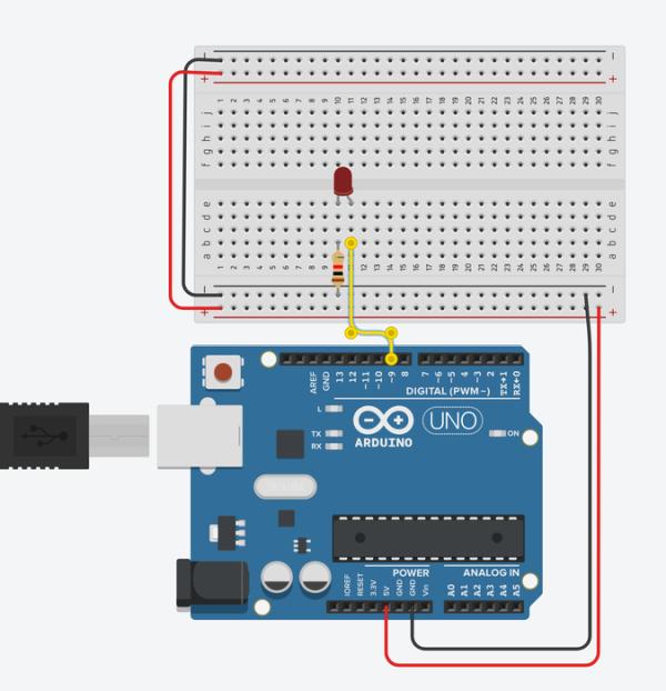
The LED is connected in series with a resistor between Arduino pin 9 and ground. Remember that the solderless breadboard rows are connected inside, so you can plug in components and wires to make quick temporary connections.
You’ll see the following connections:
- Breadboard power (+) and ground (-) rails to Arduino 5V and ground (GND), respectively
- LED cathode (negative, shorter leg) to one leg of a resistor (anywhere from 100-1K ohms is fine)
- Other resistor leg to ground
- LED anode (positive, longer leg) to Arduino pin 9
Step 2: Build Brightness Adjustment Code With Blocks
Click Start Simulation to watch the LED fade brighter and dimmer.
Let’s go over the simple program we’re using to fade the LED, which can be built in code blocks or composed using the Arduino programming language. Click Code Editor to open the code blocks editor.
Start with a control block that counts. Set it to count up by five. Click the dropdown next to “for” and select “rename variable…”, then rename it to “brightness”. Adjust the “from” and “to” values to 0 and 255, respectively.
Inside the counting loop, add an output block to set one of the special pins, and adjust it to pin 9. Navigate to Variables and drag the brightness block to the output block to set pin 9 to the current value of brightness, which changes over the course of the counting loop.
Add a wait block, and set it to 30 milliseconds. This gives time for the light to shine at each brightness level so you have time to see it before it changes. The duration of this block can be changed to slow down or speed up the fading effect.
The counting loop you created fades the LED from off to all the way on. To fade the LED back off again, we have to create another counting loop. Either drag a new counting loop into the editor, or duplicate this one, and this time change it to count down, start with 255, and go down to zero.
Step 3: Brightness Adjustment Arduino Code Explained

In the code text editor, you can see the Arduino code generated by the code blocks:
/*
  Fade
  This example shows how to fade an LED on pin 9
  using the analogWrite() function.

  The analogWrite() function uses PWM, so if  you
  want to change the pin you're using, be  sure to
  use another PWM capable pin. On most  Arduino,
  the PWM pins are identified with   a "~" sign,
  like ~3, ~5, ~6, ~9, ~10 and ~11.
*/
This first section is a comment, describing what the program does. We’ll define and explore PWM in the next steps.
int brightness = 0;

void setup()
{
  pinMode(9, OUTPUT);
}
The main body of the program starts out by creating a variable called brightness and sets it equal to zero, then inside the setup() pin 9 is initialized as an output.
void loop()
{
  for (brightness = 0; brightness <= 255; brightness += 5) {
    analogWrite(9, brightness);
    delay(30); // Wait for 30 millisecond(s)
  }
  for (brightness = 255; brightness >= 0; brightness -= 5) {
    analogWrite(9, brightness);
    delay(30); // Wait for 30 millisecond(s)
  }
}
The program’s loop uses two for loops to count up from 0 to 255 by increments of 5. The analogWrite() function takes two arguments: the Arduino pin number (9 in our case), and a value between 0 (off) and 255 (all the way on).
To program your physical Arduino Uno, copy the code from the window and paste into an empty Arduino sketch, or click Download Code and open the resulting file using the Arduino software.
Plug in and upload the sketch to your Arduino Uno board and observe your LED fade on and off.
Step 4: Fade Circuit Starter
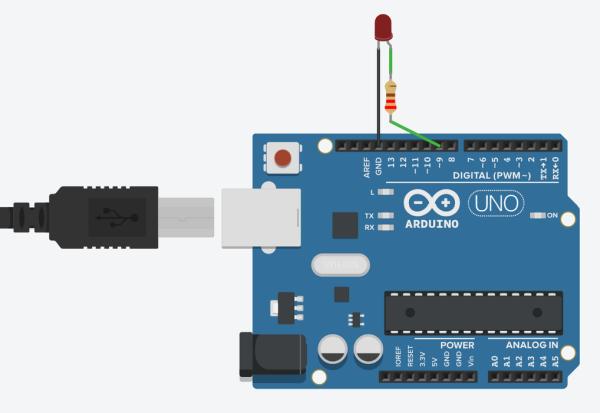
This circuit is also available as a circuit starter. You can use this circuit starter anytime you want to fade an LED.
Grab this circuit and code combo any time using the starter available in the components panel (dropdown menu -> Starters -> Arduino).
Scroll to find the Arduino starter labeled Fade, and double click it to add it to the workplane (you can also click and drag instead).
Notice how the resistor in this version is “upstream” of the LED, connected between power and the LED instead of the LED and ground. These two circuits both make the same connections, linking up the LED to a signal pin and ground, through a current limiting resistor, which will function on either side of the LED.
Source: Fading LED With Arduino Analog Output in Tinkercad
- What pin is used to fade the LED in the example?
Pin 9 is used as the PWM output to fade the LED. - How is the LED connected on the breadboard?
The LED anode goes to Arduino pin 9, the LED cathode connects through a resistor to ground, and the Arduino 5V and GND rails are tied to the breadboard rails. - Can the resistor be placed before the LED instead of after it?
Yes, the article shows a starter where the resistor is upstream of the LED; both placements function the same. - What function does the Arduino code use to set brightness?
The code uses analogWrite() with values from 0 to 255. - How does the code vary brightness over time?
Two for loops count brightness up from 0 to 255 and down from 255 to 0 in steps of 5, with delay(30) between steps. - Which Arduino pins support PWM on most boards?
Pins labeled with a tilde such as ~3, ~5, ~6, ~9, ~10, and ~11 support PWM. - What simulator does the article recommend for virtual testing?
Tinkercad Circuits is recommended to build and simulate the circuit. - What range of resistor values is acceptable for this project?
Any resistor between 100 ohms and 1 kiloohm is fine.