Summary of The EyeWriter 2.0
The EyeWriter 2.0 is a low-cost, open-source eye-tracking system enabling artists with paralysis to draw using only their eyes. Unlike the original design requiring a motionless head, version 2.0 accommodates slight head movements and glasses wearers by mounting a camera and LED system away from the user. The device costs approximately $200 in parts, significantly cheaper than commercial alternatives ranging from $9,000 to $20,000. It utilizes an Arduino board, a hacked PS3 Eye camera, and infrared LEDs to track pupil position and glints for real-time drawing.
Parts used in the EyeWriter 2.0:
- PS3 Eye Camera
- Arduino Board
- Infrared (IR) Light-Emitting Diodes (LEDs)
- Printed Circuit Boards (PCBs)
- 7.5 Volt Power Adapter
- Voltmeter
- Soldering Iron and Solder
- Red and Black Intercom Wire
- 30 Gauge Wire
- Infrared Filter Sheet
- New Lens Mount
- Hot Glue Gun
- Flathead Screwdriver
- Wire Cutters
The EyeWriter is a low-cost eye-tracking apparatus + custom software that allows graffiti writers and artists with paralysis resulting from Amyotrophic Lateral Sclerosis to draw using only their eyes.
The original design, as shown here, featured a pair of glasses as the basis for the eyewriter design:
Since that first video, we’ve been hacking on and developing the project, and we have a new design, which we’ve called “eyewriter 2.0” which improves the accuracy of the device, and allow for people who’s heads are moving slightly to also use an eye tracker. The original eyewriter, designed for a paralyzed Graffiti artist TEMPT1, is designed to be worn on a completely motionless head. The 2.0 design, which uses a camera and LED system mounted away from the head, can be used by people whose heads are moving slightly, such as MS patients, and people who wear glasses, etc.
This eyewriter system is cheap, and completely open source. At the moment, it costs about 200$ in parts. Traditional commercial eye trackers costs between $9000-$20,000, so this is a magnitude of order cheaper, and is designed to help anyone who wants or needs an eyetracker.
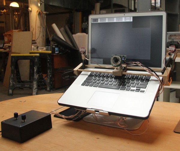
This fall, we’ve been showing off and demoing the 2.0 device — check out the eyewriter 2.0 in action — we even hooked it up to a robotic arm, to draw the artwork people make with their eyes:
http://www.switched.com/2010/12/13/eyewriter-teams-up-with-robotagger-to-print-kids-ocular-artwork/print/
(The 2.0 device was designed with help and input from Takayuki Ito, Kyle McDonald, Golan Levin and students of the eyewriter collab at Parsons MFADT. Thanks also to the Studio for Creative Inquiry / CMU for hosting a session for development)
Step 1: Overview
The basic idea approach is that we’ll be doing a few things. First, we’ll be making LED illuminators for the sides of the screen and the center. Second, we’ll be hacking the PS3 eye camera to get the vertical sync (when the frame of video is being taken) and to make it sensitive to IR. Third, we’ll be programming and building the Arduino / circuit to control the blinking. Finally, we’ll setup the base for the system and go through the basics of the software. From a technical perspective, the 2.0 system works by strobing 3 IR illuminators every frame. On even frames, it uses the center illuminator (located around the camera lens) and on odd frames it uses the 2 side illuminators. On even frames, the pupil appears bright, since the IR light is actually bouncing off the back of your eye, like red eye effect. On odd frames, your pupil appears dark. The difference between the two allows us to isolate and track the pupil in realtime. Additionally, the glints (reflections of the IR illuminators) of the dark frame are tracked, and these, plus the info on the pupil, is calibrated to screen position using a least squares fitting process for an equation that provides a mapping of glint/pupil position to screen position.
Step 2: Parts list
see parts image
download detailed parts list:
Step 3: Software – openFrameworks & EyeWriter
A. Integrated Development Environment (IDE)
- An integrated development environment (IDE) is a software application that provides comprehensive facilities to computer programmers for software development.
- Download and install an Integrated Development Environment (IDE) to run openFrameworks if necessary.
http://www.openframeworks.cc/setup
B. openFrameworks
- Openframeworks is a c++ library designed to assist the creative process by providing a simple and intuitive framework for experimentation.
- Download and install openFrameworks if necessary.
http://www.openframeworks.cc/download
C. EyeWriter GitHub
- GitHub is a web-based hosting service for projects that use the Git revision control system. It is a platform that allows people to exchange and share code.
- Visit the EyeWriter source page on GitHub.
http://github.com/eyewriter/eyewriter/tree/remoteEyetracker
- Click Download Source on the top right menu.
- Choose ZIP format.
- After download is complete, unzip the file and place the “eyewriter-xxxxxxx” folder into openFrameworks “apps” folder.
- Open the “apps/eyewriter-xxxxxxx/eyeWriterTracker/RemoteEyeTracker.xcodeproj” file to test that all installations are working correctly. The source code should load in your IDE software.
- please be sure you’re compiling for your current Operating System (the eyewriter software was originally compiled for OSX 10.5 so you might need to change compiling from ‘base SDK’ to ‘OSX 10.6’)
- Build and Run the source code. The Tracking screen should load in video demo mode.
Step 4: Software – Camera & Arduino
We will also need to install two additional pieces of hardware. Macam will allow our PS3 eye camera to talk to our computer and the Arduino software will permit our physical hardware to communicate with our software. Installing PS Eye drivers
For Mac:
- Macam is a driver for USB webcams on Mac OS X. It allows hundreds of USB webcams to be used by many Mac OS X video-aware applications. Since we are using a PS3 camera, this software will allow our computers to recognize the hardware.
- Download the Macam driver from SourceForge. http://sourceforge.net/projects/webcam-osx/files/cvs-build/2009-09-25/macam-cvs-build-2009-09-25.zip/download
- After download is complete, unzip the file and place the macam.component file into your hard drives /Library/Quicktime/ folder.
For PC:
- download the CL-Eye-Driver:http://codelaboratories.com/downloads/
Arduino
-
- Arduino is a tool for the design and development of embedded computer systems, consisting of a simple open hardware design for a single-board microcontroller, with embedded I/O support and a standard programming language
- Download and install the Arduino software. http://arduino.cc/en/Main/Software
- Follow the Getting Started tips if you’re unfamiliar with the Arduino environment. http://arduino.cc/en/Guide/HomePage
Step 5: Load Arduino sketch
In this step you will have to load the Arduino sketch for the PS eye camera to work.A. Arduino Sketch (Only for PS Eye)
-
- Load the Arduino EyeWriter sketch “apps/eyewriter-xxxxxxx/eyeWriterTracker/StrobeEye/StrobeEye.pde” in the Arduino IDE software. This needs to be done in order that the eyewritter software can recognize the hardware.
- With your Arduino board connected, upload the sketch to your board. Follow the Getting Started tips if you’re unfamiliar with the Arduino environment.
http://arduino.cc/en/Guide/HomePage
Step 6: Hardware: Power Adapter
In this step you will cut the wire of a power adapter to power your breadboard
-
- Clip off the connector jack of your 7.5 Volt Power Adapter. see image here
-
- Use a Voltmeter to determine the positive and negative wires in the adapters exposed cord.
-
- Using a short strip of red and black wire, solder the red wire to the adapters positive wire, and solder the black wire to the adapters negative wire.
- Tape the exposed wires separately to keep positive and negative apart, then tape both together to ensure no wire is exposed.
Step 7: Hardware: Infrared LED’s
IR LED’s
-
- Gather 8 Infrared (IR) Light-Emitting Diodes (LED) and a small round Printed Circuit Board (PCB).
- To build LED arrays on the PCBs youll need to know the positive and negative ends of each LED. Generally speaking the longer leg of the LED is the anode (positive), and the shorter leg is the cathode (negative). see image here On most LEDs, there will also be a flat spot on the cathodes side of the lens.
From overhead, take note of which direction the wire bond points relative to positive and negative.
-
- Setup a circuit of 4 LEDs in series, in parallel with another set of 4 LEDs in series. see image here Clip the legs of the LEDs and solder them together.
see image here
- Setup a circuit of 4 LEDs in series, in parallel with another set of 4 LEDs in series. see image here Clip the legs of the LEDs and solder them together.
-
- After soldering the LED legs together to form the circuit, solder about 2 feet (60 centimeters) of the red & green intercom wire to the LED circuits positive & negative ends. see image here
-
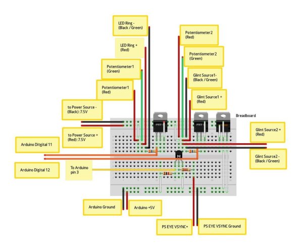
- To test the LED PCB panel, build the circuit below. Look carefully to see if your IR LEDs are glowing a faint red. see image here
-
- After confirming your IR LEDs are working, cover the back of the LED PCB panel with hot glue to keep all connections in place.
-
- Repeat steps 1 – 5 above to create another LED PCB panel.
-
- Using a larger round PCB, carefully drill press a hole into the center of the board. see image here
-
- On the outer rim of the PCB, build a circuit of 4 parallel sets of 4 LEDs in series. The placement of the LEDs should allow the PS Eye camera to fit through snugly, without the camera blocking the LEDs. see image here
-
- After soldering the LED legs together to form the circuit, solder wiring to connect all 4 positive ends together and all 4 negative ends together, putting all 4 LED sets in parallel. see image here
-
- Solder about 2 feet (60 centimeters) of the red & green intercom wire to the LED circuits positive & negative ends.
-
- To test the larger LED PCB panel, build the circuit below. Look carefully to see if your IR LEDs are glowing a faint red. see schematic here
-
- After confirming your IR LEDs are working, cover the back of the LED PCB panel with hot glue to keep all connections in place.
Step 8: Hacking the PS Eye camera – preparing
In this step we will talk about how to take apart a PS Eye camera. This is necessary for you to be able to replace the lens on the camera, insert a infrared filter and wire the v-sync.
-
- Get a PlayStation (PS) Eye camera. Use at your own risk because the camera will undergo modifications voiding its warranty.
-
- Pry the four plastic screw caps off the back of the casing. see image here
-
- Unscrew the four screws underneath where the screw caps were. Keep these screws because you will need some later.
-
- With all four screws removed, pry off the back half of the casing. A flathead screwdriver and hammer, or a pair of pointed pliers should work. It requires significant force so be very careful not to damage anything inside or hurt yourself. see image here.
-
- Pull the cord aside and unscrew the two bottom screws beside the plastic holder. Keep these screws also. see image here
-
- Remove the stand piece.
-
- Unscrew the five screws around the board (two screws on the side, three screws on top). Keep these screws also. see image here
-
- With all five screws removed, lift the board out of the front casing.
-
- There are four microphones across the top of the board. Using wire cutters, clip off the microphones because they won’t be used. see image here
- Now the PS Eye board is prepared for wiring. The next steps will connect wiring to the Vertical Synchronization (V-Sync) and Ground joints on the PS Eye board.
Step 9: Hacking the PS Eye camera – VSync
-
- In this step we will go through getting the v-sync off the camera. The v-sync is an electrical signal that comes from the camera which communicates the camera’s refresh rate. Getting the camera’s v-sync is crucial for this application to work because it is the only way we can match the camera’s refresh rate to our infrared LED’s.
-
- Locate the Ground joint on your PS Eye board. Some PS Eye models have 5 joints near the lens mount (left image below), while some have 4 joints (right image below). If your model has 5 joints, the Ground joint is at the end closest to the lens mount. If your model has 4 joints, the Ground joint is also at the end closest to the lens mount, and twice as wide as the other joints. see image here
- Cut about 2 feet (60 centimeters) of your 4-color intercom wire, and split the red and green from the black and white.
- Split the red and green wire about 2 inches (5 centimeters) from one end, and strip off a small section of insulation at the end of the green wire. The green wire will be soldered to the PS Eyes Ground joint.
- Clip the PS Eye board and green wire to a stand, and prepare to solder the green wire tip to the Ground joint. Use a piece of thick paper or cardboard in between the clips teeth to prevent scrapes on the board. see image here
- Solder the green wire to the PS Eyes Ground joint.
- Locate the V-Sync via on the board. Its the via circled in the image below. see image here. Attention: for more recent models of the PSEye camera (identified by the golden rim around the board) the VSync hotspot can be found on the front of the PCB, directly above the R19 resistor. see image here. Very REcently a newer model was also introduced in the market (v9.2)see how to identify it in this image and how to find the vSync spot in this image
- Using a sharp knife, carefully pivot the knife tip on the via, and scrape off enough insulation coating to expose the metal contact below. see image here
- The red wire needs to connect to the exposed V-Sync via, but the wire is too thick to be soldered neatly to the small via, so a 30 gauge wire will be used in between. Strip the ends of a 2 piece of 30 gauge wire.
- Shorten the red wire, then solder one end of the 30 gauge wire to the end of the red wire. see image here
- Before soldering the 30 gauge wire to V-Sync, a test should be performed to ensure all connections are correct. Build the circuit below. When the 30 gauge wire contacts the V-Sync via, the LED on the breadboard should flicker rapidly. see schematic here
- Using thin 0.022 inch (0.56 millimeters) solder, carefully solder the 30 gauge wire to the exposed V-Sync via. To confirm, ensure the LED on the breadboard is flickering.
Step 10: Hacking the PS Eye camera – finishing
-
- In this step we will talk about how to put your camera back into one piece.
-
- Unscrew the 2 screws holding the lens in place. Be careful not to break the fragile V-Sync connection. Detach the lens and keep both screws. see image here
-
- Measure the square opening of the new lens mount. Cut a square from the filter sheet that is minutely smaller, and place it into the lens mount opening. see image here
-
- With the filter in place, screw in the new lens mount. This will require some force, and one screw will go in at an angle because the new lens mount is a little too big for the board. see image here
-
- Screw the new lens into the new lens mount on the board.
- Use hot glue to cover and secure the V-Sync connection. see image here
For more detail: The EyeWriter 2.0
- How much does the EyeWriter 2.0 cost compared to commercial trackers?
The device costs about 200 dollars in parts, while traditional commercial eye trackers range between 9000 and 20000 dollars. - Can people with moving heads use the EyeWriter 2.0?
Yes, the 2.0 design allows people whose heads are moving slightly, such as MS patients, to use the tracker. - Does the system work for people who wear glasses?
Yes, the 2.0 design was specifically created to be usable by people who wear glasses. - What software is required to run the EyeWriter 2.0?
The system requires an Integrated Development Environment (IDE), openFrameworks, and the EyeWriter source code from GitHub. - How does the system track the pupil in real time?
The system works by strobing three IR illuminators every frame; the difference between bright and dark frames allows it to isolate and track the pupil. - Why is the V-Sync signal important for the PS3 Eye camera?
The V-Sync signal is crucial because it communicates the camera's refresh rate, allowing it to match the infrared LEDs. - What modification is made to the PS3 Eye camera lens?
The original lens is removed, and an infrared filter sheet is placed into a new lens mount to make the camera sensitive to IR. - How many IR LEDs are needed to build the arrays?
You need to gather eight Infrared Light-Emitting Diodes to build the necessary LED circuits.