Note: Try any or all of these at your own risk. I will not be responsible for any issues.
Get a professional to help if you are unsure.
The concept is that we take a controlling voltage from the computer or a micro-controller, which drives an electrically isolated circuit with Relay or Triac.
You must choose a Relay circuit, if you have a big coffee-machine (greater than 200W or so), otherwise you can use a triac-based one.
All circuits presented are at least once tested, but it’s YOURS RESPONSIBILITY the results. If you have no experience with electronics you should NOT try with these, otherwise you may get a bad one…
You should be very careful while experimenting with 220V, and there is no obsolesce in using an appropriate fuse.
(Thanx to tldp.org)
Note: though the pinouts would be different, these circuts could beADAPTED for microcontollers such as the Arduino MSP430, Beaglebone, Rasperry Pi, and etc.
Step 1: Driving voltage 0-5V from the computer.
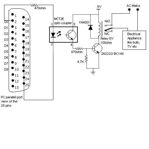
A simple example to get a voltage 0-5V from the parallel port of the computer. (See picture)Pin 1 is Strobe (inverse logic)
Pins 2-9 is DATA BUS’s signals, exactly what was written to the parallel port’s latches with an OUTB command.
Pin 10 is the acknowledge signal (ACK), controlled by you, so that you can produce an interrupt to the CPU.
Pins 18-25 are short-circuited and this is the ground (GND).
Step 2: Controlling with a relay.
Connect Vcc with the same voltage as the relay type (usually 5 or 12V). Obviously, the relay’s specifications should be reasonable for your coffee-machine.
Barmen, usually, tend to put the relay AFTER the transistor, at the emitter (E) pin instead of the collector (C) pin. This is a bad practice because it biases the transistor badly, and may result in bad coffee :-). Diode 1N4002 is useful to protect the transistor from the relay’s currents. If you don’t use it the transistor will become darker and smelling…
Step 3: Controlling with TRIAC v1.
If you only want a simple circuit, you can use Motorola’s triac driver MOC301012 (or other opto-isolator), together with a general purpose TRIAC like SC141D (NTE5608). This method has the advantage that you don’t need an extra power supply.
For non-inductive loads this is the circuitry: (See picture)
If you are going to work with 220V, prefer a 3021. Inductive loads should be used in conjuction with bypass capacitors, see Motorola Application Note AN-780. Coffee-machines are mainly resistive loads and not inductive (like a motor), but who knows what’s yours…
Step 4: Controlling with TRIAC v2.
The MC3032 is an optoisolator TRIAC driver. The 180-ohm resistor sets the current for the LED emitter in the optoisolator. Change the value of this resistor – if necessary – to get reasonable current (e.g., 15 mA).
Note that you cannot test this circuit without a load. The TRIAC will not switch unless connected to an AC voltage source, so you can’t test it for simple switching w/o applying AC and a load. Note the 500V rating on the .01 cap.
Step 5: Etc
Here are three examples of controlling a relay from the PC’s parallel printer port (LPT1 or LPT2). Figure A shows a solid state relay controlled by one of the parallel port data lines (D0-D7) using a 300 ohm resistor and 5 volt power source. The solid state relay will energize when a “0” is written to the data line. Figure B and C show mechanical relays controlled by two transistors. The relay in figure B is energized when a “1” is written to the data line and the relay in figure C is energized by writing a “0” to the line. In each of the three circuits, a common connection is made from the negative side of the power supply to one of the port ground pins (18-25).
There are three possible base addresses for the parallel port You may need to try all three base addresses to determine the correct address for the port you are using but LPT1 is usually at Hex 0378. The QBasic “OUT” command can be used to send data to the port. OUT, &H0378,0 sets D0-D7 low and OUT, &H378,255 sets D0-D7 high. The parallel port also provides four control lines (C0,C1,C2,C3) that can be set high or low by writing data to the base address+2 so if the base address is Hex 0378 then the address of the control latch would be Hex 037A. Note that three of the control bits are inverted so writing a “0” to the control latch will set C0,C1,C3 high and C2 low.
Step 6: Using ssr’s.
Using solid state relays (aka ssr’s) are probably the easiest way to go. Be sure to get ones for the correct voltage you need. Follow the instructions per the manufacturers directions. Get a professional to help if you are unsure.
Step 7: Odds and ends
Parallel port organ.
(From Tomi Engdahl)
Connectors: D25 male
Resistors: 640k,320k,160k,80k,40k,20k,10k,5k,390 (+-1%)
(You can use different values of resistors, but the ratio of the values of the resistors must be same. 0.5, 1, 2, 4, 8, 16, 32, 64 etc.) 1, 2, 4, 8, 16, 32, 64, 128
Capacitor: Electrolytic or solid Tantalum 10 uF 10V
AVR programmer (see picture) (resistors are most 1k)
For more detail: External device control (i.e. coffee machine)


