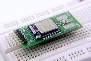
The rise of the ESP8266 WiFi chip was almost overnight with Espressif’s open approach and pushing from Hackaday. While no ground-breaking product has yet emerged, the development on the chip are phenomenon. However due to an unknown reason the ESP8266 modules manufacture seems to prefer non-standard 2.0mm pitch connector, which gives a lot of headache to breadboarding lovers like me. This forced me to make a breadboard friendly ESP8266 breakout board.
The modules I’m targeting are ESP-07 and ESP-12, both having identical pinout but only differ in antenna type. I choose these two because they have all the I/O available, and using same edge castellation (half vias) connectors which is easy to work with.
The modules are 16mm tall, easily occupies 4 rows (2 rows on each side) on a breadboard. Therefore my first design requirement is to minimize real estate on the breadboard. To do this I made some custom pin headers by modifying from SMT pin header.
I removed pair of pins from both ends and replace with through hole pins. This little touch strengthens the bounding between pin header and the board. If otherwise on my first version I can easily pull up all the pads when lifting the board up from breadboard. With this design, I maintain 4 rows occupation on the breadboard, that leaves another 6 rows for wiring
For more Details: ESP8266 breadboard adapter and I’m on Tindie

