Summary of Enhancing Safety: Arduino-Based Smart Helmet for Accident Detection
The article describes an Arduino-based smart helmet that detects alcohol and accidents, sends GPS location and calls via a GSM SIM800L module, and uses NRF24L01 for transmitter-receiver communication. The transmitter (Arduino Mega) reads MQ3 alcohol and SW-420 vibration sensors plus GPS, then triggers GSM messages/calls. The receiver (Arduino Nano) uses NRF communication and a relay to control a 12V motor simulating bike ignition. Code for both transmitter and receiver, wiring tables, and GSM AT commands are provided.
Parts used in the Smart Helmet:
- Arduino Mega (transmitter)
- Arduino Nano (receiver)
- MQ3 Alcohol Sensor
- Vibration Sensor SW-420
- GSM SIM800L Module
- GPS NEO-6M Module
- NRF24L01 wireless module (two units)
- Single channel Relay module
- 12V DC motor with gears (to simulate bike engine)
- Servo motor
- Wires, power supplies (5V, 3.3V, 12V) and breadboard/connectors
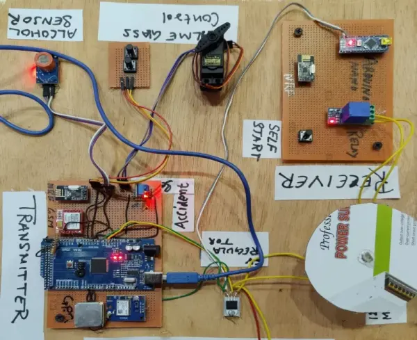
Hello everyone, welcome back to Techatronic. The smart helmet encompasses a range of functionalities including navigation, call management, accident detection, alcohol sensing, and various other features aimed at transforming the helmet into a smart device. Prioritizing the safety and security of the rider, this helmet serves as a crucial aid. For instance, it prevents bike ignition if the rider is inebriated, ensuring safety on the road. Loaded with multiple features, the primary objective of this smart helmet project revolves around ensuring the driver’s safety.
The helmet integrates various electronic elements like GPS, GSM, and multiple sensors. Additionally, for the GSM module, a functional 2G or 3G SIM card is necessary. Our aim consistently revolves around addressing community issues through innovation. Prior projects, including the Sign Language Glove and Blind Stick, demonstrate our commitment to solving challenges. These same principles guide the development of this smart helmet.
This innovative concept introduces a smart helmet project utilizing Arduino for accident detection. Designed to mitigate potential damages during accidents, this helmet not only safeguards the wearer but also initiates calls to relatives and transmits location data through a GSM module.
How does the system will work?
Initially, let’s focus on the transmitter section designed for deployment within the helmet. Within this segment, we’ve integrated two sensors: an alcohol sensor and an accident detection sensor. The alcohol sensor, recognized as the MQ3 sensor, requires some understanding of its attributes and functionalities.
Components Required for smart helmet :-
MQ3 sensor (Alcohol Sensor)
The MQ3 sensor is uniquely designed to detect alcohol solely from the moisture present in the air. It identifies the moisture content specific to alcohol, detecting this element using a metal electrode housed within the sensor, which becomes active upon contact with alcohol.
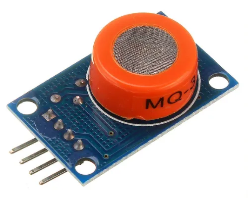
Electrons flow between the electrodes within the MQ3 sensor. Upon alcohol contact, the conductivity of the electrode increases. This change in conductivity is detected at the output pin, aiding the detection process in the Arduino-based smart helmet project. The MQ3 sensor can be easily interfaced with Arduino or any other controller being utilized here.
The MQ3 sensor operates at an input voltage of 5V, provided through the Vcc pin. Extended usage of the MQ3 sensor over long durations may lead to potential malfunctions.
Vibration Sensor SW-420
Another crucial sensor to note is the vibration sensor, specified as the SW-420 model. The operational mechanism of this vibration sensor is notably straightforward.
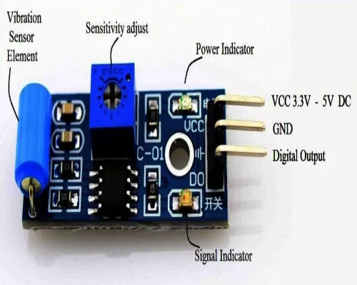
Enclosed within the cylindrical structure are numerous small metal balls. The sensor contains multiple metal lines, where each pair is linked to the ground and signal wire. Upon vibration, these balls make contact with both lines, completing the electrical circuit and generating a signal at the output pin.
This vibration sensor serves as a trigger for the GSM module. Continuously transmitting signals to the Arduino—our designated microcontroller in this smart helmet project—the vibration sensor prompts actions in response to signal variations.
If the sensor detects vibrations within the smart helmet, close to an accident scenario, the Arduino activates the GSM module to send messages and initiate calls.
GSM SIM800L Module.
Incorporated within this smart helmet project is the GSM SIM800L Module, utilized for location tracking. Activation of this module is initiated through the vibration sensor.
The GSM SIM800L Module is a low-power device capable of supporting 2G and 3G SIM cards, facilitating communication functionalities.
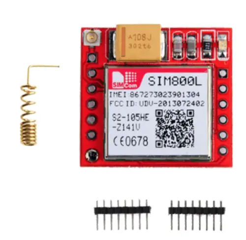
The GSM SIM800L module, characterized by its compact size and affordability, serves as a GSM module enabling device connectivity to GSM networks. This module possesses the capability to communicate through SMS, voice calls, or GPRS with other devices. It supports quad bands covering the 850/900/1800/1900 MHz frequency bands.
Operating over both 2G and 3G bands, the SIM800L module adopts the UART protocol, utilizing Rx and Tx pins for data transmission and reception.
This module is compatible with power inputs ranging from 3.3 volts to 5 volts, requiring a minimum power supply of 2 amps. For optimal performance, it’s recommended to utilize a 5V 2A external power supply to power the module.
For those interested in programming the GSM module, a comprehensive list of AT commands and instructions is provided below for reference.
| Command | Description |
| AT+CSMS | To Select message service |
| AT+CPMS | To Preferred message storage |
| AT+CMGF | select Message format |
| AT+CSCA | Service center address |
| AT+CSMP | Set text mode parameters in sim |
| AT+CSDH | To Show text mode parameters in Sim |
| AT+CSCB | Select cell broadcast message types |
| AT+CSAS | Save settings in the gsm module |
| AT+CRES | Restore all settings |
| AT+CNMI | Message indications to TE |
| AT+CMGL | To make the list of messages |
| AT+CMGR | Read new message |
| AT+CMGS | Send a new message |
| AT+CMSS | Send message from sim storage |
| AT+CMGW | Write a message to gsm memory |
| AT+CMGD | Delete message |
Note that although the module offers user-friendly features, it demands a basic understanding of electronics and programming. Additionally, ensure compatibility with a suitable SIM card and a stable cellular network connection within your vicinity.
Within the program, we’ll include the designated phone number to which SMS and calls will be directed.
GPS Module neo 6m module
The Arduino-based helmet project incorporates the Neo 6M module to transmit the current location.
The NEO-6M GPS module is compact and cost-effective, capable of receiving GPS signals to determine precise latitude, longitude, and time data. It seamlessly operates with the Global Positioning System (GPS) and is compatible with the Global Navigation Satellite System (GNSS).
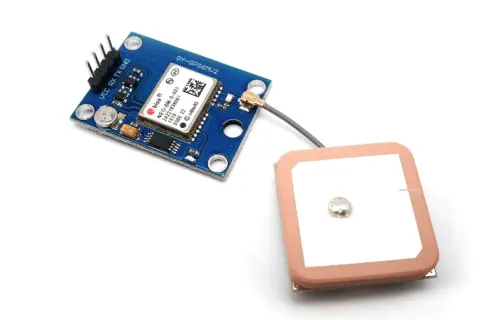
The GPS Neo 6M module communicates via the UART protocol, establishing connectivity with any microcontroller. In this project, the module interfaces with Arduino through the UART protocol, utilizing the RX and TX pins for connectivity.
A dedicated library assists in calibrating the sensor via code implementation.
The NEO-6M GPS module finds widespread application in navigation systems, geotagging, tracking devices, and unmanned aerial vehicles (UAVs). It’s essential to highlight that the module’s optimal performance necessitates an unobstructed view of the sky for receiving GPS signals. Consequently, its functionality might be limited indoors or in regions with poor satellite coverage.
NRF module NRF24L01
In the smart helmet project, there exist two devices: a transmitter and a receiver, both requiring data transmission. To facilitate bidirectional communication between them, we’re employing NRF modules.
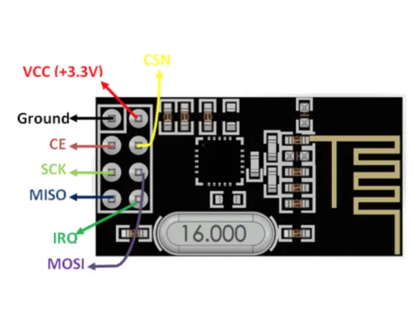
The NRF modules are compact, affordable, ultra-power devices operating on a 2.4 GHz wireless transceiver. These modules are suitable for wireless communication projects, enabling connections among multiple NRF modules for seamless communication.
Utilizing the SPI (Serial Peripheral Interface) protocol, NRF modules establish communication among devices. In this setup, one NRF module is linked to the transmitter, while the other connects to the receiver module.
Single channel Relay module
Here in the receiver section we are using a relay which will be trigger the motor which is to be pretend the bike engine.
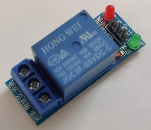
Upon receiving data from the transmitter to initiate motor action, the relay module needs to be activated. The relay module is essential for operating the 12V DC motor.
DC motor 12v
We’ve implemented a 12V DC motor with gears in this setup. When the driver is detected as being inebriated, the motor will automatically switch off, resulting in the bike engine being turned off.
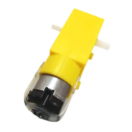
The 12V DC motor is linked to a 12V external power source, facilitated via a relay that consistently activates the motor. The Arduino cannot directly operate the DC motor due to potential back electromotive force (EMF) issues and the low current capacity at its pins.
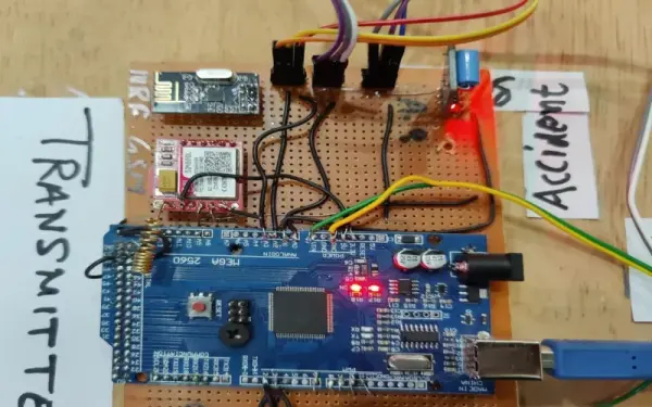
Arduino Mega for Tranmitter
At the transmitter site, we’ve opted for the Arduino Mega. Numerous electronic components with different communication protocols, like NRF, GSM, GPS, and more, need to be connected.
The Arduino Mega offers over 60 pins, facilitating seamless communication with various devices, making it well-suited and compatible with our project requirements.
Arduino Nano
The Arduino Nano, featuring the Atmel ATmega328P microcontroller chip, is a compact and diminutive microcontroller board. Resembling the well-known Arduino Uno, it boasts a smaller physical size. This board is crafted for straightforward programming via the Arduino Integrated Development Environment (IDE), utilizing a USB connection for ease of use.
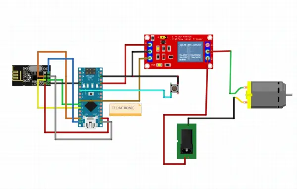
Smart Helmet Project Circuit Diagram (Transmitter)
![]()
Presented here is the circuit diagram for the receiver circuit of the smart helmet. It includes components such as the alcohol sensor, push button, servo motor, GPS, GSM, and NRF module.
Connection Table
| Arduino Mega | MQ-3 Alcohol Sensor |
| 5V | VCC |
| G, GND | GND |
| A0 Pin | A0 Pin |
| Servo motor | |
| 5V | Red |
| GND | Black |
| DATA | Orange |
| GSM SIM800L | |
| 2 | Rx |
| 3 | Tx |
| 5v | Vcc |
| GND | Gnd |
| GPS NEO 6M Module | |
| 10 | Rx |
| 11 | Tx |
| 5v | Vcc |
| GND | Gnd |
| Vibration Sensor | |
| A1 | Din |
| 5v | Vcc |
| Gnd | Gnd |
| NRF Module | |
| 50 | MISO |
| 51 | MOSI |
| 52 | SCK |
| 8 | CSN |
| 7 | CE |
| 3.3V | Vcc |
| Gnd | Gnd |
Now we have to make the Transmitter connection to complete the project.
Smart Helmet Project Circuit Diagram (Receiver)
Connection Table
| Arduino Nano | Relay Module |
| D6 | In |
| 5v | Vcc |
| Gnd | Gnd |
| NRF 24L01 | |
| 12 | MISO |
| 11 | MOSI |
| 13 | SCK |
| 7 | CE |
| 8 | CSN |
| 3.3v | Vcc |
| Gnd | Gnd |
Smart Helmet Project Code
#include
#include
#include
#include
#include
#include
RF24 radio(7, 8); // CE, CSN
const byte address[6] = “00001”;
Servo myservo;
int pos = 0;
int state = 0;
const int pin = A1;
float gpslat, gpslon;
TinyGPS gps;
SoftwareSerial sgps(10, 11);
SoftwareSerial sgsm(2, 3);
void setup() {
// put your setup code here, to run once:
pinMode(A0, INPUT_PULLUP);
pinMode(A1, INPUT_PULLUP);
pinMode(A2, INPUT_PULLUP);
pinMode(A3, INPUT_PULLUP);
myservo.attach(9);
sgsm.begin(9600);
sgps.begin(9600);
radio.begin();
radio.openWritingPipe(address);
radio.setPALevel(RF24_PA_MIN);
radio.stopListening();
Serial.begin(9600);
myservo.write(180);
delay(500);
}
void loop() {
// put your main code here, to run repeatedly:
int m = analogRead(A0);
int n = analogRead(A1);
int o =digitalRead(A2);
int p =digitalRead(A3);
Serial.print(m);
Serial.print(” “);
Serial.print(o);
Serial.print(” “);
Serial.print(n);
Serial.print(” “);
Serial.println(p);
delay(100);
if(o==0)
{
myservo.write(180);
delay(500);
}
else if (p==0)
{
myservo.write(0);
delay(500);
}
sgps.listen();
while (sgps.available())
{
int c = sgps.read();
if (gps.encode(c))
{
gps.f_get_position(&gpslat, &gpslon);
}
}
if(m>=500)
{
const char text[] = “H”;
radio.write(&text, sizeof(text));
delay(100);
}
else
{
const char text[] = “A”;
radio.write(&text, sizeof(text));
delay(100);
}
if(n>=700)
{
sgsm.listen();
sgsm.print(“\r”);
delay(1000);
sgsm.print(“AT+CMGF=1\r”);
delay(1000);
/*Replace XXXXXXXXXX to 10 digit mobile number &
ZZ to 2 digit country code*/
sgsm.print(“AT+CMGS=\”+919560718291\”\r”);
delay(1000);
//The text of the message to be sent.
sgsm.print(“Latitude :”);
sgsm.println(gpslat, 6);
sgsm.print(“Longitude:”);
sgsm.println(gpslon, 6);
delay(1000);
sgsm.write(0x1A);
delay(4000);
sgsm.println(“ATD +919560718291;”); //replace x by your number
delay(20000);
//digitalWrite(5,HIGH); // LED1 ON
sgsm.println(“ATH”);
delay(2000);
Serial.println(“calling…..”);
}
else
{
Serial.print(“”);
}
}
Once the provided code has been uploaded to the transmitter component of the project, the next step involves uploading the provided code into the Receiver section.
Smart helmet code for Receiver
#include
#include
#include
RF24 radio(7, 8); // CE, CSN
const byte address[6] = “00001”;
void setup() {
pinMode(6, OUTPUT);
pinMode(3, INPUT_PULLUP);
Serial.begin(9600);
radio.begin();
radio.openReadingPipe(0, address);
radio.setPALevel(RF24_PA_MIN);
radio.startListening();
}
void loop() {
int c= digitalRead(3);
if(c==0)
{
while(1)
{
if (radio.available()) {
char m;
radio.read(&m, sizeof(m));
Serial.println(m);
//char m = text;
if(m==’H’)
{
while(1)
{
digitalWrite(6, HIGH );
delay(200);
int c= digitalRead(3);
if(c==0)
{
break;}
}
}
else if(m==’A’)
{
digitalWrite(6, LOW );
delay(200);
}
}
}
}
else
{
digitalWrite(6, HIGH );
delay(200);
}
}
- How does the smart helmet detect alcohol?
The MQ3 alcohol sensor senses alcohol in air by changes in electrode conductivity and provides an analog output to the Arduino as described in the article. - How does the helmet detect accidents?
The SW-420 vibration sensor detects shocks when metal balls complete circuits during vibration and signals the Arduino to act as explained in the article. - Can the helmet send location information after an accident?
Yes; the NEO-6M GPS module provides latitude and longitude which the Arduino sends via the GSM SIM800L as described in the article. - How are messages and calls sent from the helmet?
The GSM SIM800L module is controlled via AT commands over a serial connection from the Arduino to send SMS and place calls as shown in the article. - What role does the NRF24L01 play in the project?
NRF24L01 modules provide wireless communication between the helmet transmitter and the receiver using SPI, as described in the article. - How does the receiver disable the bike engine when intoxication is detected?
The receiver activates a relay driven by the Arduino Nano to switch off the 12V DC motor (simulating the bike engine) when the transmitted signal indicates intoxication. - Which Arduino boards are used for transmitter and receiver?
The transmitter uses an Arduino Mega and the receiver uses an Arduino Nano as specified in the article. - What power requirements are specified for the GSM SIM800L module?
The SIM800L supports 3.3V to 5V input and requires a minimum 2 amp supply; a 5V 2A external power supply is recommended in the article. - Does the GPS module work indoors?
The NEO-6M needs a clear view of the sky for optimal performance and may be limited indoors or in poor satellite coverage per the article.