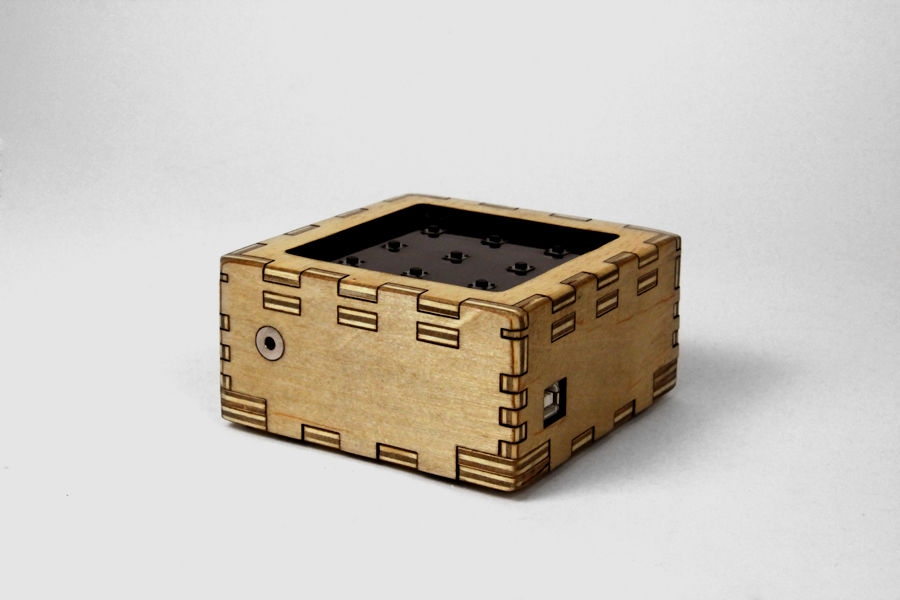
This electronic instrument allows you to sequence and loop audio and MIDI data. Most of the time I use it to sequence drum samples so I can play around with different beats and rhythms. The really great thing about this instrument is that it is very portable, it fits in your hands easily, runs off a single 9 volt battery, and has a headphone jack that you can plug into. If you connect it to your computer via usb you can also use it to send MIDI data, this way you can communicate with other electronic instruments or software environments that understand MIDI.
Parts List:
(x1) Arduino Uno (Duemilanove is fine, but make sure it is ATMEL328P) Radioshack #276-128
(x1) Arduino ProtoShield Radioshack #276-140
(x1) PC Board with Copper Radioshack #276-147
(x9) High Tact Switch Radioshack #275-002 (I really liked the feel of these buttons, but they only come in a surface mount version, which makes them fairly difficult to solder because of the small leads. Additionally, since these buttons are square it is harder to drill a hole for them in an enclosure. If you are a beginner, you might want to use a different type of button, any of these momentary switches will work)
(x1) 10KOhm Audio Control Potentiometer with SPST Switch Radioshack #271-215 (this will be used to control volume and turn the device on/off)
(x1) 50K-Ohm Linear-Taper Potentiometer Radioshack #271-1716
(x2) 220µF 35V 20% Radial-lead Electrolytic Capacitor (or anything between 200 and 300 uF) Radioshack #272-1029
(x2) SPST PC-Mountable Submini Toggle Switch Radioshack #275-645
(x2) Silver Tone Knurled Knob (or any knob with 0.25″ inner diameter) Radioshack #274-424
(x9) 1N914/4148-Type Diode (two packages) Radioshack #276-1122
(x3) 2K ohm 1/2W 5% Carbon Film Resistor (1 package)
(x10) 10K Ohm 1/4-Watt Carbon Film Resistor (2 packages) Radioshack #271-1335
(x8) 20K Ohm 1/4-Watt Carbon Film Resistor (2 packages)
(x1) 4.7K Ohm 1/4-Watt Carbon Film Resistor Radioshack #271-1330
(x1) 1K Ohm 1/4-Watt Carbon Film Resistor Radioshack #271-1321
(x1) 5K Ohm 1/4-Watt Carbon Film Resistor
(x1) 9V Alkaline Battery Radioshack #23-853
(x1) Heavy-Duty 9V Snap Connectors Radioshack #270-324
(x1) Amber Super-bright LED Indicator Radioshack #55050630
(x1) White Super-bright LED Indicator Radioshack #55050633
(x1) 1/8″ Stereo In-Line Audio Jack Radioshack #274-274
(x1) LM386 Low Voltage Audio Power Amplifier (8-Pin DIP) Radioshack 276-1731
(1x) 8 Pin Socket 276-1995 Radioshack 276-1995
Additional materials:
22 Gauge Wire Radioshack #278-1224
Solder Radioshack #64-013
drill
plywood
polyurethane finish
sand paper
hot glue
super glue
four wood screws
Heat Shrink Wrap Radioshack #278-1610
Electrical Tape Radioshack #64-2375
I’ve included fritzing breadboard diagrams (divided into a few parts) and schematics for this project as well as all firmware. You can find these documents throughout the body of this instructable or download them all in one zip file below.
![]() all files.zip2 MB
all files.zip2 MB
Step 1: Build enclosure
I used AutoCAD, Autodesk 123D Make, and CorelDRAW to design my project enclosure. I’ve attached the AutoCAD, STL, and the EPS files for the enclosure I built below. Then I sent my EPS files to a laser cutter and cut them out of 0.2″ plywood. I also cut a front panel out of 3mm acrylic. If you do not have access to a laser cutter, you can buy a project enclosure or find a spare box and drill holes in it for all your components, be creative!
I wanted to sand off the scorched ends of the laser cut pieces so that the outside of the box had a consistent finish, so I also made a set of eps files with some extra length on the ends for sanding (“enclosure long”).
I glued the pieces together with wood glue and cut a piece of acrylic for the front panel.
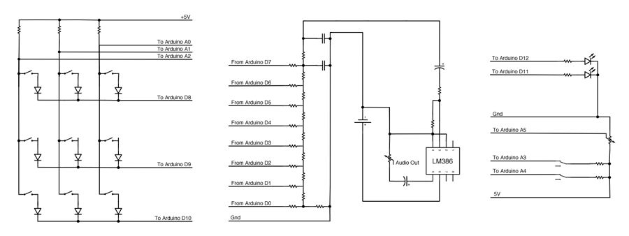
As shown in figures 11 and 12, multiplexed buttons are wired such that each button shares a common lead with all the buttons in its row, and it shares the other lead with all the buttons in its column. This way we can use the Arduino to ground one row of buttons at a time (Arduino D8, D9, D10) and check to see if any of the columns are grounded by measuring the voltage of A0, A1, and A2. Essentially, we will be measuring the states of the buttons row by row. Since the Arduino is very fast, we will not be able to tell a difference in the response time of the buttons when they are multiplexed vs if we had dedicated one input pin to each button.
Multiplexing buttons does bring some complications. Since current can flow in both directions through a button, if two buttons are depressed at the same time, current can flow through the circuit in ways we did not intend and make us think that four buttons are depressed. In order to prevent this, each button is attached to a diode, ensuring current always flows through the buttons in one direction.
Buttons work in the same way as switches, they close an open circuit. Most buttons have two leads (figure 9), but some (like the ones I used) have four leads because each side of the switch is split into two separate leads. By comparing figures 9 and 10, you can see that both types of buttons are essentially the same, but if you use the four lead buttons, be sure to check the specs to locate two leads that are not connected to each other. Solder a diode to one side of each switch, be sure that the “-” end (usually indicated with a stripe) is facing away from the switch. Solder a (preferably black) wire to the other end of the diode and a (preferably red) wire to the other side of the switch. Do this for all nine switches. You may find it necessary to use hot glue, electrical tape, or heat shrink to reinforce/protect these connections.
Once soldered, mount each button in your project enclosure.You can find the fritzing files for 2-lead button and 4-lead button multiplexing below.
Step 3: Prepare arduino shield
Solder the red wires (the lead not connected to the diode) from the buttons to the protoboard. Solder the leads from buttons 0, 3, and 6 in line with analog pin 2, buttons 1, 4, and 7 with analog pin 1, and buttons 2, 5, and 8 with analog pin 2. Clip the excess wire from each of these connections and solder all the adjacent points together on the underside of the board (see figure 2). Each of the buttons should now be electrically connected to an analog pin and one of the 2k resistors.
Again, I’ve provided the circuit diagrams and fritzing documents for both 2-lead and 4-lead buttons.
Solder the black wires (the lead connected to the diode) from the buttons to the protoboard. Solder the leads from buttons 0, 1, and 2 in line with digital pin 8 buttons 3, 4, and 5 with digital pin 9, and buttons 6, 7, and 8 with digital pin 10. Clip the excess wire from each of these connections and solder all the adjacent points together on the underside of the proto-shield (see figure 2). Each of the buttons should now be electrically connected to one of the digital pins.
2-lead and 4-lead diagrams and fritzing are provided here, again.
Step 7: Sand enclosure
Step 8: Mount and wire LEDs
I mounted my indicator LEDs early so I could sand the tops down while finishing the wood in the rest of the enclosure. Sanding down the top of LEDs gives them a frosted surface which makes them nice and diffuse. I used some super glue to fit the LEDs inside two 5mm holes, I left the top parts sticking out so that it could be sanded flush with the enclosure surface.
Attach the shorter leads of both LEDs to each other (grounds) and connect to the ground pin of the Arduino protoshield. Attach a current limiting resistor to each of the longer leads of both LEDs. The optimum resistor value can be calculated as follows:
R>=V/I
where:
R is resistance across the resistor measures in ohms
V is forward voltage in volts from LED specs
I is continuous forward current measured in amps from LED specs
For most through hole LEDs the forward voltage will be about 2-3.5V and the current will be 15-25mA. You can check the datasheet of the LEDs you bought to calculate the lowest possible resistor values for your LEDs. I chose to use resistors that were much higher than I needed, because I didn’t want the LEDs to be blindingly bright. I ended up using a 1k resistor for the amber LED and a 4.7k resistor for the white LED, these values may be different depending on what type of LEDs you use and how bright you want them, but 1k is a good place to start.
I’ve attached the fritzing document which includes the LED wiring below.
Step 9: Tempo pot
Step 10: DAC
The resistor ladder for this project is an 8-bit DAC. As you can see in the schematic, Arduino PORT D (digital pins 0-7) output 8 pieces of data (one from each pin) which are sent to each junction of the DAC. I soldered these resistors on a piece of copper plated protoboard I cut down to size.
I added two 0.1uF capacitors to the end of the resistor ladder to act as a low pass filter. This type of filter will remove the higher frequencies caused by the low (8khz) sampling rate of the audio and smooth out the waveform. You may choose to change the values of these capacitors depending on what you like. There are 10 connections to the DAC, 8 digital input pins from the Arduino, ground, and audio out. The green wire in figure 6 is audio out, this wire will connect to the amplifier in the next step. You can find the fritzing file below.