Summary of Electrocardiograph & Heart Rate Monitor
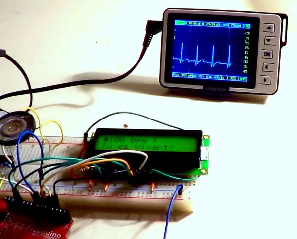
This Instructable guides users in building a simple, breadboard-sized electrocardiograph and heart rate monitor as an educational science project. It emphasizes safety by using battery power only and warns against medical use. The device utilizes an Arduino Uno to process signals from instrumentation amplifiers, displaying results on an LCD while providing audio and visual feedback via a speaker and LED.
Parts used in the Electrocardiograph & Heart Rate Monitor:
- Instrumentation amplifier INA128
- Operational amplifier 741
- Arduino Uno
- 16x2 characters Liquid crystal display
- Voltage regulator 7805
- 8 ohms mini speaker
- Bright LED (10 mm)
- Diode 1N3064
- 9V Batteries with connectors
- Breadboard
- Jump wires
- Resistors (100 ohm, 470 ohm, 1 kiloohm, 10 kiloohm, 100 kiloohm, 1 Megaohm)
- Capacitors (10 nF, 47 nF)
- Speaker wire
- Antistatic wrist strap
- Medical tape
- Aluminum paper
- Metallic paper clips
- Shower gel
This instructable shows you how to make an electrocardiograph and a heart rate monitor. It is intended to be a fun science project only. Of course, it should not serve as a medical purpose.
PLEASE NOTE : To avoid any risk of electric shock, only use battery alimentation. Electrodes are theorically isolated from the circuit by the instrumentation amplifier, but play safe. I’m not responsible for any accident that may happen.
This is a simple design that fits on a single breadboard. You are free to experiment and to custom it for your needs.
Since it’s my first Instructable and also since English is my second langage, don’t hesitate to contact me if you find an error or if you want some clarifications about a section or another. I will be happy to edit my project for the better!
Step 1: List of Materials
– (1) Instrumentation amplifier INA128
– (1) Operational amplifier 741
– (1) Arduino Uno
– (1) 16×2 characters Liquid crystal display
– (1) Voltage regulator 7805
– (1) 8 ohms mini speaker
– (1) Brigth LED (I use a 10 mm one)
– (1) Diode 1N3064
– (2) 9V Batteries with connectors
– Breadboard
– Jump wires
Resistors :
– (2) 100 ohms, 1/4W
– (1) 470 ohms, 1/4W
– (1) 1 kiloohms, 1/4W
– (2) 10 kiloohms, 1/4W
– (2) 100 kiloohms, 1/4W
– (1) 1 Megaohms, 1/4W
Capacitors :
– (1) 10 nF
– (1) 47 nF
For the electrodes :
– About one meter of speaker wire
– Antistatic wrist strap
– Medical tape
– Aluminum paper
– (2) metallic paper clips
– Shower gel (a substitute for electrocardiogram gel)
Optional but recommended:
-Oscilloscope, for the electrocardiography part of the device
Step 2: Build the Circuit
Here is the schematic of the circuit and a suggestion of the breadboard implementation. The two electrodes will be plugged on pin 2 and 3 of the INA128. An additionnal reference electrode (an antistatic wrist placed on your right leg) will be plugged in ground. This configuration allows you to use unshielded cables.
The best signal is just after the low-pass filter (between the two 100kOmhs resistors). I suggest that you plug the oscilloscope probe at this point for demonstration, although you might want to check other points to see if everything is working properly.
For more detail: Electrocardiograph & Heart Rate Monitor
- What is the primary purpose of this project?
This is intended to be a fun science project only and should not serve any medical purpose. - Can I use mains electricity for this circuit?
No, you must only use battery alimentation to avoid any risk of electric shock. - How do the electrodes connect to the circuit?
The two electrodes plug into pin 2 and 3 of the INA128, while a reference electrode plugs into ground. - What is the best place to check the signal with an oscilloscope?
The best signal is located just after the low-pass filter between the two 100kOhm resistors. - What can substitute for electrocardiogram gel?
Shower gel can be used as a substitute for electrocardiogram gel. - Is an oscilloscope required to build the device?
An oscilloscope is optional but recommended for the electrocardiography part of the device. - Can I customize the design?
Yes, the design fits on a single breadboard and you are free to experiment and customize it for your needs. - Why is the antistatic wrist strap placed on the right leg?
It acts as an additional reference electrode plugged into ground to allow the use of unshielded cables.