Summary of Easy Arduino LED Dice
This article guides users in building an Arduino-based LED dice that displays a face when a pushbutton is pressed. The project involves assembling seven LEDs in an H-formation on a breadboard, connecting them via short and long jumper wires to specific Arduino pins, and wiring a push button with a resistor for input detection.
Parts used in the Arduino LED Dice:
- 11 long jumper wires
- 7 short jumper wires
- 7 LEDs
- 1 breadboard
- 1 Arduino Uno
- 1 USB cable for the Arduino
- 1 push button
- 1 resistor
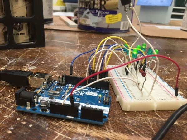
This instrcutable will show you how to hook up LEDs to show a face of a dice when a pushbutton is pressed.
Step 1: Supplies
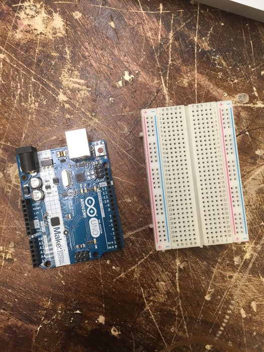
For this project you will need to following:
11 long jumper wires
7 short jumper wires
7 LEDs
1 breadboard
1 Arduino Uno
1 USB cable for the Arduino
1 push button
1 resistor
Step 2: Start With Assembling Your LEDs
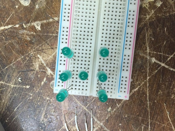
You will take your LEDs and place them in a H formation.
LED1: pins 1 and 2
LED2: pins 5 and 6
LED3: pins 9 and 10
LED4: pins 4 and 7
LED5: pins 3 and 4
LED6: 7 and 8
LED7: 11 and 12
Step 3: Start Wiring the LEDs
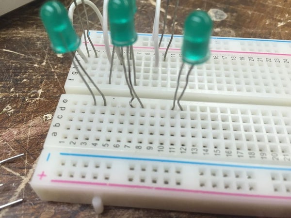
You will take your 7 short wires and start placing them on one side of the LED. One end of the wire will go in the negative channel on the board and the other on the same row as a LED leg. To connect the opposite side of the LEDs place a wire in the same row as a already connected wire and place it in the same row as the LED leg.
Step 4: Hook Up the Wires That Will Connect to the Arduino
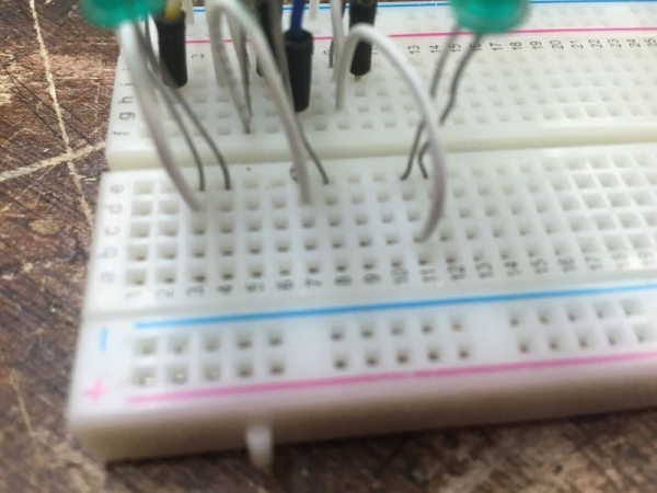
Now you will take 8 of the 11 long wires and place them in your board on the other leg of the LED. Each LED needs one long wire and one short wire connected to it. Once the long wires are hooked up to the board you will place them in pins 1-7 on your Arduino.
LED1 in pin 1
LED2 in pin 2
LED3 in pin 3
and so forth
Once you have those 7 wires connected you will take the 8th wire and connect it to the ground on the pin side of the Arduino. One end of the wire will go in the negative channel that the short wires are plugged into and the other end in the Ground pin next to pin 13 on your Arduino.
Step 5: Hooking Up the Push Button
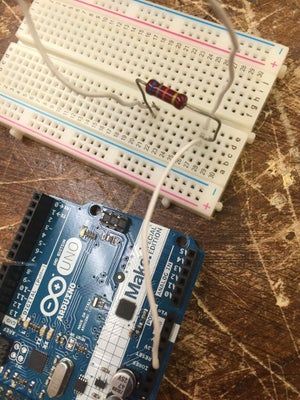
Take the resistor and place it into channel 21 and channel 27. In each channel place one end of the push button. Take one of the long wires and place it in channel 27 and connect it to the 3.3V pin on your Arduino. Take another long wire and place it from the positive channel to the Ground next to the 5V pin on your Arduino. In channel 21 place a long wire going from that channel to pin 8.
Source: Easy Arduino LED Dice
- How should the LEDs be arranged on the breadboard?
The LEDs must be placed in an H formation across specific pin numbers. - Which Arduino pins are used for the seven LEDs?
Pins 1 through 7 are used to connect one long wire from each LED leg. - How do you connect the ground for the LED circuit?
A wire connects the negative channel of the short wires to the Ground pin next to pin 13. - Where is the resistor placed in the circuit?
The resistor is placed into channel 21 and channel 27 to work with the push button. - Which Arduino pin receives the signal from the push button?
A long wire connects channel 21 to pin 8 on the Arduino. - How is power supplied to the push button circuit?
A long wire connects channel 27 to the 3.3V pin on the Arduino. - What is the purpose of the 8th long wire?
The 8th long wire connects the common negative channel to the Ground pin on the Arduino. - Can this project be built without a USB cable?
No, a USB cable for the Arduino is listed as a required supply for the project.