Summary of E-dice – Arduino Die/dice 1 to 6 Dice + D4, D5, D8, D10, D12, D20, D24 and D30
This Arduino project creates a versatile electronic die capable of simulating 1 to 6 standard dice or selecting from 8 special polyhedral dice (D4, D5, D8, D10, D12, D20, D24, D30). Users select options via a rotary encoder, view results on an 8x8 LED matrix with animations, and trigger rolls using a pushbutton. The design uses an Arduino Nano and a MAX7219 driver for efficient pin usage, allowing the system to be housed in a compact cube if soldered, though the tutorial demonstrates a breadboard setup.
Parts used in the Electronic Die:
- Arduino Nano
- Rotary Encoder (or click-encoder)
- Pushbutton
- 8x8 LED Matrix with MAX7219 Module
- Wire Jumpers
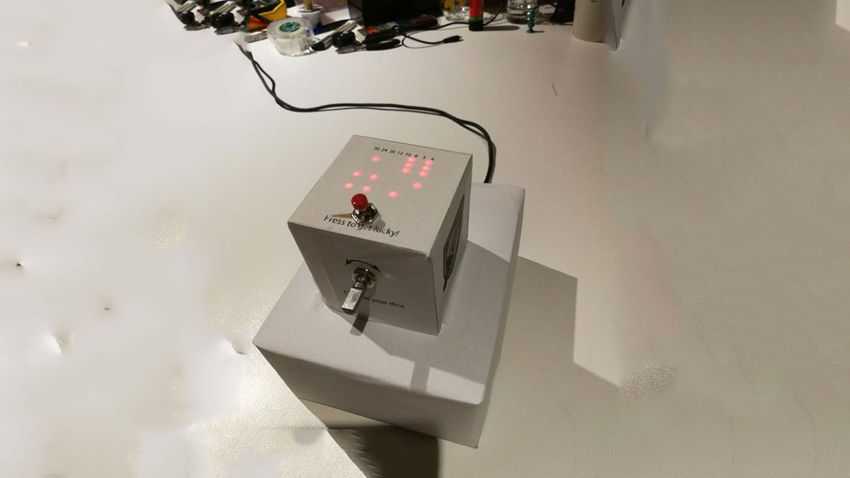
This is a simple arduino project to make a electronic die. It is possible to choose for 1 to 6 dice or 1 out of 8 special dice. Choice is made by simply turning a rotary encoder.
These are the features:
- 1 die: showing big dots
- 2-6 dice: showing dots as well as total value (alternating)
- 4, 5, 8, 10, 12, 20, 24 and 30 faced dice showing value and indicator for chosen die
- animation for rolling dice when pressing the button
It is possible to fit everything in a 7cm by 7cm cube including a battery. But then you would have to solder everything. I used a breadboard and some jumper wires to connect everything, hence the bigger box underneath.
To seed the arduino random numbers, I used the readout of an unconnected free pin.
Remark: This instructable will show you every step to make the e-dice work. I will add a pdf with a basic pattern for the box, however without further instructions. By putting a layer of paper over the led matrix, you make numbers and results more visible.
Supplies:
- arduino (I used a nano)
- rotary encoder (or click-encoder but we don’t use the push function)
- pushbutton
- 8 x 8 led matrix with MAX7219 Module (fewer pins needed! 3 instead of 8)
- wire jumpers
Step 1: Step 1: Plug in Components
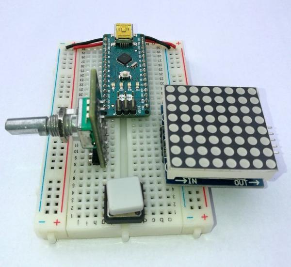
- Plug in all components so none of the pins are connected to each other. (Holes a to e are connected per line number, the same for holes f to j)
- The arduino nano goes at the top with pins on both sides of the central pin.
- The (click)encoder or rotary encoder goes left
- The led matrix on the right
- Push button at the bottom for easy access (determin which contacts are opened by pushing)
- Use a piece of wire to connect the two “+” lines
- Do the same for the two “-” lines (ground or gnd)
Step 2: Step 2: Connect 8×8 Led Matrix to Arduino
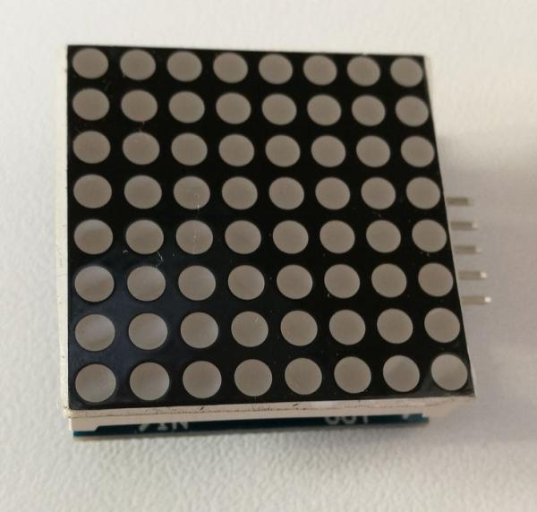
We use a led matrix with a MAX72XX driver. We can save up 5 pins and don’t have to multiplex.
It is possible to connect multiple matrices to one MAX72xx driver. For this there is an “OUT” and “IN” side. We only use the “IN” pins.
These pins are pushed into the breadbord. You can see the pin names just under the led matrix itself. All have to be connected:
- VCC to 5V (“+”-line)
- GND to GND (“-“-line)
- DIN to Arduino D12 (orange jumper)
- CS to Arduino D10 (green jumper)
- CLK to Arduino D11 (white jumper)
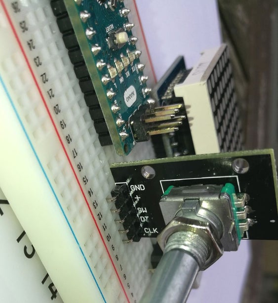
Step 3: Step 3: Connect Rotary Encoder
I used a rotary click encoder. These encoders have an extra push function (and extra pin) which we don’t use in this project. You could do with an ordinary rotary encoder.
When you turn the knob, the encoder will give + or – signals compared to the original position. You can feel notches when turning. In my case I found out with Serial.print() that the encoder gave 4 steps for each notch. You have to adjust this if some of the dice types are skipped. (See code)
Connect the encoder as followed:
- GND to GND (“-“-line) (small piece of black wire)
- + to 5V (“+”-line) (small piece of red wire)
- SW to nothing (this is the switch, which we don’t use.)
- DT to A1 (orange jumper)
- CLK to A0 (white jumper)
Read more: E-dice – Arduino Die/dice 1 to 6 Dice + D4, D5, D8, D10, D12, D20, D24 and D30
- How are random numbers seeded in this project?
The project seeds random numbers by reading the output of an unconnected free pin. - Can I use fewer than 8 pins for the LED matrix?
Yes, using the MAX7219 module allows you to save up to 5 pins, requiring only 3 connections instead of 8. - What types of dice can this project simulate?
It supports 1 to 6 standard dice, as well as special 4, 5, 8, 10, 12, 20, 24, and 30 faced dice. - How does the user switch between different dice types?
The choice is made simply by turning a rotary encoder. - What happens when the button is pressed?
Pressing the button triggers an animation for rolling the dice. - Do I need to solder everything to fit it in a small box?
Yes, fitting everything into a 7cm by 7cm cube including a battery requires soldering all components. - How many steps does the encoder give per notch?
In this specific case, the encoder gave 4 steps for each notch, which may require code adjustment. - Which Arduino pins connect to the MAX7219 driver?
DIN connects to D12, CS to D10, and CLK to D11.