
Summary of Dual H-Bridge – Arduino L298 Breakout Board
This article details the construction of a homemade Dual H-Bridge circuit using the L298N IC, designed to control DC or stepper motors. The guide covers creating a custom perfboard layout, soldering components in a specific order (diodes, connectors, capacitors, resistors, then IC), and connecting top and bottom layer tracks with colored wires. It also provides links for advanced Eagle CAD schematics.
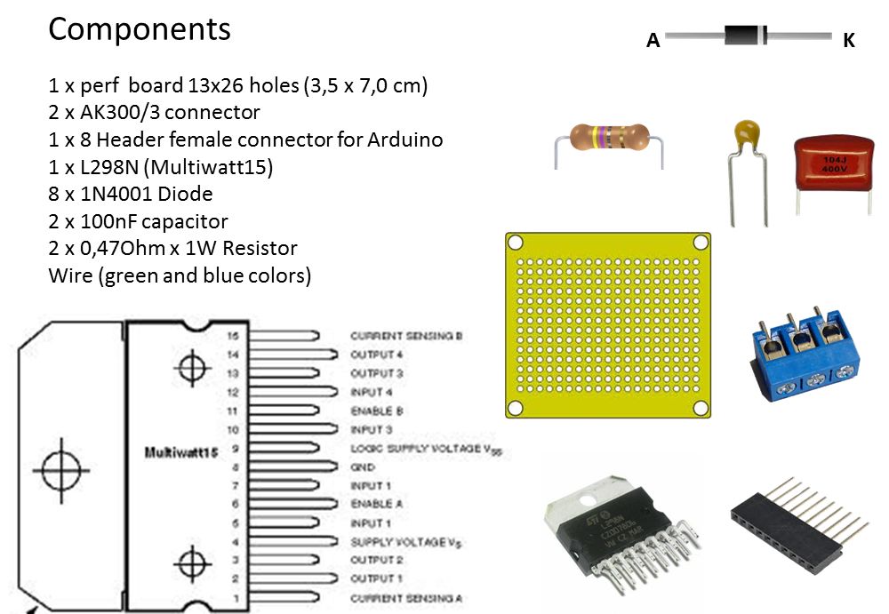
Parts used in the Dual H-Bridge Project:
- 1 x perf board 13x26 holes
- 2 x AK300/3 connector
- 1 x 8 Header female connector for Arduino
- 1 x L298N (Multiwatt15)
- 8 x 1N4001 Diode
- 2 x 100nF capacitor
- 2 x 0,47Ohm x 1W Resistor
- Wire (green and blue colors)
This is my homemade Dual H-Bridge using the IC L298N.
For control DC motors or step Motors ao other purposes just like you need.
 Breakout L298N.ppt
Step 1: Hardware and Materials
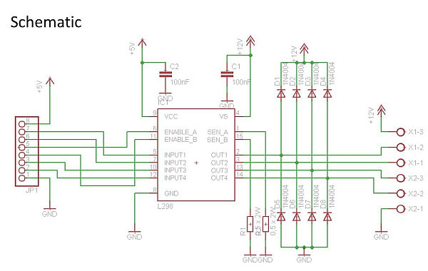
This is the basic schematic. It works perfectly.
A more advanced schematic and board for eagle cad, you can download from the link below.
http://www.4shared.com/file/T17oVW-z/PONTE_H_L298N.html
http://www.4shared.com/file/6VdOTgv5/PONTE_H_L298N.html
1st Step – Perfboard, holes location
Make a Board with 3,5 x 7,0 cm or 13 x 26 holes.
Locate in this board, all holes that we will use for the components.
Components
After sanding and cleaning the board, put all components in it according of the diagram above and schematic.
For this, bend components properly.
Do the soldering for each group of components independently, for example:
diodes first and then connectors and then capacitors and resistors and finally the L298N IC; or in what order you want or you are used to do.
Soldering and wired Tracks
Following the schematic and diagram above, first of all make all soldered tracks in the bottom layer of the board.
After that, solder the jumper wires making the wired tracks.
Note.
Green wires are on the top layer and blue wires are on the bottom layer of the board.
2 x AK300/3 connector
1 x 8 Header female connector for Arduino
1 x L298N (Multiwatt15)
8 x 1N4001 Diode
2 x 100nF capacitor
2 x 0,47Ohm x 1W Resistor
Wire (green and blue colors)
For more detail: Dual H-Bridge – Arduino L298 Breakout Board
- What is the primary purpose of this project?
The project is designed to control DC motors, step motors, or other purposes. - How should I prepare the perfboard before soldering?
You must sand and clean the board, then locate all holes needed for components according to the diagram. - Does the article recommend a specific order for soldering components?
Yes, it suggests soldering groups independently, such as diodes first, then connectors, capacitors, resistors, and finally the L298N IC. - Can I download an advanced schematic for Eagle CAD?
Yes, links are provided to download a more advanced schematic and board design from 4shared. - Which wire colors correspond to which board layers?
Green wires are placed on the top layer and blue wires are on the bottom layer of the board. - What are the dimensions of the perfboard required?
The board should be 3.5 x 7.0 cm or have 13 x 26 holes. - How many diodes are required for this build?
Eight 1N4001 diodes are required for the project. - What type of connector is used for Arduino connection?
An 8 Header female connector for Arduino is used.
