Hey Everyone what’s up.
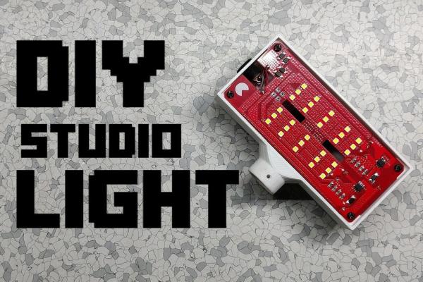
This is my DIY Studio Light Project
Which basically is a do-it-yourself studio light that is made from a custom 3D Printed body and a custom PCB which were both provided by PCBWay.
Question
Is it better to Buy an expensive Studio Light or Make your own DIY Studio Light with custom 3D Printed parts and PCB?
Well, the goal for making this project was just that, I wanted to make a DIY Studio Light for my current “Maker Setup” as the lighting in my lab bench is not very great.
Commercially available light costs above 50$ (good ones) but why spend money on them when you can make your own Studio Light, Body can be made from a 3D Printer and the circuit can be manufactured by a PCB manufacturer.
In this Instructables, I’m gonna show you guys how I made this DIY Studio Light in few easy steps.
Let’s Get started!
Supplies
These are the things that I used for this built
- LEDs (NICHIA JK3030 3V .2W LED)
- 1.5 Ohms Resistance 1206 Package
- 0.47 Ohms Resistance 1206 Package
- 100uf Capacitor
- 63uH Indictor
- SS34 Diode SMA
- DC Barrel Jack
- Custom PCB (which was provided by PCBWAY)
- Custom 3D Printed body (which was also provided by PCBWAY)
- SIC9301A led driver IC x2
- 12V DC FAN (Generic small one)
- 12V SMPS Power Supply
Step 1: Basic Structure
My goal was to make a DIY Studio Light completely from scratch to compete with existing light available in the market.
The reason for starting this project was the cost of the existing setup, Commercial Studio Light isn’t exactly cheap and I need at least 2-3 Lights which would cost a lot so I made an easy-to-make Studio Light with custom PCB and 3D Printed Body.
Also, I’m using a generic FR4 PCB here. these LEDs produce a lot of heat so why I’m not using MCPCB (metalcore) instead of FR4 (fiberglass) for making a better-LED PCB that can disperse heat better than FR4 Board?
You see, I have added lots and lots of Via in this PCB, these Via will conduct heat from the top side and transfer that heat to the bottom portion which will result in Heat getting Disperse equally. Then at the backside, there’s a 12V Mini DC FAN which cools down the PCB heat.
Apparently, Metal PCBs or MCPCBs are not $$$ wallet-friendly and if I have used a metal PCB in this project, I also have to use another FR4 board for LED Driver IC setup. So I saved a lot by making a single PCB that contains the LEDs and Driver IC setup.
Also, the Body of this light is made from PET-G which is quite a durable plastic so overall, this DIY Studio Light can sustain heat.
Step 2: Schematic
The main schematic of this project is attached above and as you can see, it’s not very complex. it contains two LED Driver IC setups both with their LOAD (LEDs) connected separately.
Their Input side is connected with each other which is the common Input VCC and GND. we will supply 12V to these two terminals to run this board.
(yes, I haven’t used any Microcontroller or any Switching IC in this Circuit)
Step 3: PCB Designing
With the above Schematic, I prepared the PCB in my CAD software.
The board outlines were already designed in the Fusion360, I used its measurements as a reference to make the PCB.
I placed LEDs at the center of the board and maintained an equal distance between them, to keep things symmetrically accurate.
And as you can see, I’ve placed lots of Vias in this PCB. Vias cover almost 70% of this PCB and they are here for Conducting heat as well as connecting one side with another side of the board.
Anyways, after finishing the PCB, I exported its Gerber data and send it to PCBWay for samples.
I Received the PCB in 7 days which is pretty fast, and it also came with a PCB Scale which was pretty cool (I have used my beans to get that scale though)
I have to say, PCBs that I’ve received were great as expected, PCBWay, you guys rocks.
Check out PCBWay for getting great PCB Service for less cost!
Next is the PCB Assembly Process.
Step 4: PCB ASSEMBLY
Before starting the Assembly process, I gather all the stuff that was being used in this PCB, LEDs ICs Resistance Diodes.
- We start first by adding Solder paste to each component’s pad one by one. (check this project video for detailed version of this process)
- Then we place components in their right location in the right order, this pick and place process is pretty long as I used 30 LEDs in this project but after this, all we need to do is reflow this PCB.
- After this, I carefully lifted this PCB which has components on top and place it on my DIY SMD HOTPLATE.
- Hotplate heats up this PCB up to the Solderpaste melting temperature which is around 200-250°C. Solder paste melts and connects the component Pads with PCB Pads.
- After ensuring that the whole PCB has been reflow properly (which took like 2 minutes) I carefully removed the PCB from Hotplate and let it cool down for few minutes.
- End result of this Hotplate Reflow process will be a nicely reflown PCB.
- The next Process is to add THT Components on the backside of the PCB in the Right Order. Four capacitors and two inductors.
- And our Circuit is basically completed.
Now, to ensure that the soldering process was done without any short, I tested this circuit with a 12V Battery Pack by connecting the VCC and GND with battery packs 12V+ and GND.
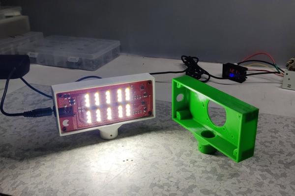
Step 5: Custom Enclosure/Body
Next is the Main Body of this project which holds the Circuit in front and a Fan at the backside.
I designed this whole project in Fusion360, the body was made in such a way that we can mount a Generic 12V Mini DC Fan on the backside, it also has two holders (these two) which we can mount on a wall with these mounting holes.
For this project, the ideal material is PET-G because of its good thermal resistance to a higher temp (it still melts but its temperature resistance is far better than regular PLA).
I have an Ender 3 and it just couldn’t print a perfect PET-G Model so I used an external CNC Service this time.
I used PCBWay’s 3D Printing Service. PCBWay also provides CNC/3D Printing services apart from PCB manufacturing and PCB Assembly.
So I uploaded my STL files for the body on PCBWay’s FDM Quote Page and selected the material for this print job which was PET-G.
I ordered the 3D Printed Main Body for this project and received the package in about a week.
Here’s the Custom Body that I have received, it looks pretty good considering that PET-G is hard to print material and they have nailed it.
The quality of this print is very HIGH!
This Service is useful for those who don’t own a 3D Printer or who want an SLA 3D Print which cannot be made in an FDM Printer or a metal 3D Print.
Check out PCBWay’s 3D Printing Service for ordering custom 3D Printed/CNC Parts for a low Price.
Now let’s get back to our main topic. which was to add a 12V DC Fan at the backside with some M3 Nut and bolts.
after this, we add our circuit in front with M3 Screws, but before adding the PCB with Enclosure, I added a barrel DC Jack which will be used to connect power to this setup.
I added DC Fan’s VCC and GND port with the Vin and GND Port of PCB, and the added positive terminal of Barrel Jack with Vin of Main PCB and GND of barrel jack to GND of main PCB. (Wiring Diagram is attached)
After adding wires, I screwed the circuit onto the 3D Printed Body and our Studio Light Setup was basically completed.
Step 6: RESULT and Testing It Out
This light is small and lightweight as it doesn’t have any Lithium battery inside it but it’s alright as I’m gonna power this setup with an External 12V 5A SMPS.
For Running this Studio Light, I used this Metal SMPS which is rated at 12V 5A, I added this DC Jack to the VCC and GND of SMPS and then connected the DC Jack with Barrel Jack.
Now, In order to check this setup voltage and current consumption, I added this digital Voltmeter with this wiring diagram.
Right now this whole setup is drawing 11watts of power which is OK for now.
The current consumption can be changed by adjusting these Resistances so if I want more power then I have to reduce the Resistance value in parallel.
Like right now I’ve added 1.5 Ohms x3 Resistance and 0.47 Ohms Resistance in parallel which is around 0.24Ohms Total Resistance. To Increase the Power, we need to make this 0.24Ohms into 0.1Ohms which can be achieved by reducing the Resistance value.
So I swapped two 1.5 Ohms Resistance with 1 Ohms Resistance on both Driver IC.
And guess what, Now LEDs are drawing 1.23A at 12V which is 14.7W.
An increase in Power is a little bit but it also increases the Light Intensity and lumens.
But anyway, this is my current setup lighting, and when I add the Studio Light in front of this TTGO Board, Lighting increases drastically.
Lighting Quality can be better if we add this light on the TOP side or prepare two more for each side, left and right.
Step 7: Role of FAN
Why did I add a fan on the backside?
The fan circulates air from the back to the front side which keeps PCB Cool from the Bottom side which is beneath the LEDs.
This was a very crucial thing to do because as you already know, LEDs tend to heat up, and these LEDs that I’m using heat up very quickly. even though the PCB has so many vias to disperse heat properly, this PCB still needs a cooling source which is in this case an OLD 12V DC fan that I salvaged from my old Anet A8 Printer, it even has the company’s logo.
Step 8: Conclusion
So the 100$ Question here is, is it better to buy an existing studio light or built your own with few LEDs and a Custom body and PCB?
And the answer is YES, we can just Make our Own DIY Studio Light which will save cost and you can build multiple Light Box Setup for a better lighting solution.
Step 9: So What’s Next?
For Part 2, I will be adding a PWM Dimmer to this STUDIO LIGHT Project and use two-color LEDs in it (Warm white and cool white). Also, I will increase the Length of this whole structure so I could add more LEDs to it and increase its Power and Lumens.
Well, that’s it for today guys, Hit that subscribes button if this video was helpful, also check out this project’s page for a more detailed version of this project along with the documentation and CAD Files.
Stay safe and ill be back with another cool project.
Sayonara my dewds.
Source: DIY Studio Light/ Light Box