Summary of DIY- G-force measurement system
This article details a DIY g-force measurement system using an Arduino UNO and a 3-axis accelerometer to log data onto an SD card. Originally designed for RC car tuning, the system captures acceleration, cornering, and shock data via Ch3 of a radio receiver. The project requires intermediate electronics skills due to specific voltage requirements and memory constraints, recommending ATmega328 or higher microcontrollers. Future plans include a wireless real-time analysis version.
Parts used in the G-Force Measurement System:
- Arduino UNO w/ATmega328P
- 3-axis accelerometer breakout (ADXL335)
- SD card
- SD card breakout w/level shifting circuit
- LED
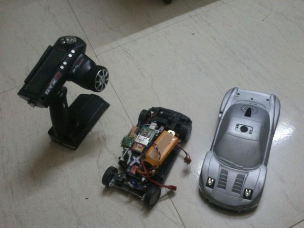
So this time around, it’s another fun and functional microcontroller based DIY, a g-force measurement system with data logging to SD card.
HARDWARE USED:
1) Arduino UNO w/ATmega328P
2) 3-axis accelerometer breakout
3) SD card
4) SD card breakout w/level shifting circuit
5) LED
HOW IT WORKS:
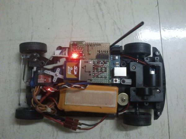
Basically, the system uses an accelerometer to measure g-force and a SD card to store the data. An Arduino UNO is used to process the data coming from the accelerometer and save it on to a SD card. The system was originally developed for setup tuning and performance optimization in RC cars. It makes use of Ch3 on the Rx for initiating or terminating the data logging sequence, which means you’ll need a three channel radio to make this work. However, if you’re familiar with Arduino, you can easily modify the code to substitute appropriate control actions and happily use it wherever and with whatever you want.
Technically, I’m using an ADXL335 3-axis accelerometer that can measure upto +/-3g. It doesn’t have an impressive output resolution, but I find it good enough for my application. The system reads data from all the three axes, which means it can measure a decent amount of useful data.
In RC cars, cornering forces, forward/reverse acceleration, breaking/collision forces, vertical shocks and suspension damping analysis data can be acquired. All this data is logged on to the SD card in independent .txt files for each axis.
Step 1:
HOW TO USE:
Mount the gForce gauge on to your RC car, wire it up to Ch3 on Rx, press Ch3 on your Tx to initiate data logging, do some hard acceleration/ breaking or take on some high speed corners or whatever you want to measure and press Ch3 again to terminate the data logging sequence. A small LED is used to indicate the data logging in process. Unplug the SD card, connect it to a computer and You have the data that you can analyse and make necessary changes to your RC car to make it run faster and smoother.
The Arduino schematic does not show the level-shifting circuit required for the SD card, but it’s necessary, refer to the “SDcard Breakout DIY” schematic.
Format the SD card to FAT32 file system before using. Please use older less capacity SD cards like 2 GB or less. Not tested with SDHCs yet and MicroSD cards with SD adapter can be used, but again, 2GB MicroSD cards or less only. A few more warnings have been mentioned in the Arduino sketch itself, they’re worth noticing.
The Arduino code compiles to a binary sketch of roughly 17.24 KB in size, so the Arduino boards based on ATmega8 and ATmega168 will not work due to their limitations in flash memory size. I have tried to shrink the code as much as possible, but my smallest sketch is 15.79 KB and it’s 1.5 KB too much to fit on a ATmega168. I’m no expert, so if someone is capable of shrinking the code significantly, please do share it with me. For now, an ATmega328/Arduino Uno is apt and an ATmega2560/Arduino Mega with it’s plethora of I/Os is plenty.
Please watch the voltage ratings of your I/O devices. My ADXL335 breakout board came with an on-board 3.3v voltage regulator, which is why my schematics show it connected to the 5v supply. The same applies to SD card breakout board.
Step 2:
CONCLUSION:
It’s not that much of a complicated DIY, but you need intermediate electronics skills at minumum. Quite a few things can go wrong, I wouldn’t suggest you try this as your first electronics based project. However, nobody is stopping you- frying a microcontroller chip is a crime not punishable by law!
COMING UP:
Additionally, I’m in the process of developing a real-time g-force analysis system using wireless transceiver modules like Xbee and putting all the hardware on a single PCB, no more bulky deveopment board hassle. Coupled to the telemetry system is a software interface that reads the incoming data in real-time and outputs the same in the form of a graph on a computer screen. The same bit of software can also be used to read the SD card data and generate a graph.
For more detail: DIY- G-force measurement system
- How is data logging initiated and terminated?
Data logging is started and stopped by pressing Ch3 on the transmitter. - What type of SD card capacity is recommended?
Older cards with 2 GB or less capacity are recommended as SDHCs were not tested. - Can this project work with an ATmega168 based board?
No, the code requires roughly 17.24 KB of flash memory which exceeds the ATmega168 limit. - What file system must the SD card be formatted to?
The SD card must be formatted to the FAT32 file system before use. - How are the collected data files stored?
Data is logged on the SD card in independent .txt files for each axis. - Does the ADXL335 breakout board require a separate 3.3v regulator?
No, the specific breakout board mentioned includes an onboard 3.3v voltage regulator. - What kind of radio is needed for the default setup?
A three channel radio is required to utilize Ch3 for initiating the sequence. - What is the future plan for this project?
The author is developing a real-time system using Xbee modules and a single PCB.