As mentioned on the Contents page, two different hardware platforms have been successfully used to support Mk2 PV Routers.
[Update at 7/3/14: Since writing this article, I have developed a new hardware platform which has been specifically designed for this product. The main board has an integral power supply and RF module, and there is a display to show how much surplus energy has been diverted each day. Two of the PCBs can be mounted directly inside an enclosure from Schneider Electric; this can be either ABS or polycarbonate.This new venture of mine is fully described at www.Mk2PVrouter.co.uk where there is a Shop which can supply all of the necessary components either in kit-form or pre-built and tested. The information below is still entirely valid, and this article is referenced from my website as supporting material.]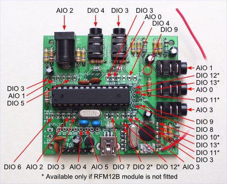
The emonTx was originally thought by the author to be less suitable for the Router application than a bespoke hardware platform. However, both the emonTx and the Arduino Uno versions have since been shown to give equivalent performance, so the choice is really down to how well the features of each version match the requirements for each constructor’s needs.
All of the author’s software runs equally well on either platform.
All of the necessary information to construct a basic Mk2 router may be found in the initial posting on the OEM forum at http://openenergymonitor.org/emon/node/841 and this is essentially the same for whichever version is chosen. This includes a schematic diagram which covers the circuitry for both of the input sensors and the output stage. The sensors for voltage and current are entirely standard and are well described in the Building Blocks section. Buffering the 2.5 V reference is not essential. Many constructors have used two independent references, as may be found on the emonTx platform, with no problems.
Although the input stage is both low-voltage and non-invasive, the output stage will require some connection to the mains supply. If at all unclear about how this should be done, it would be wise to seek guidance from a qualified electrician.
Some form of power supply will be needed for the processor. For setup purposes, power via the programming lead from the USB socket of a laptop or PC is fine, but for continuous use, a permanent power supply should be arranged.
The OEM shop stocks various items which may be of use:
- Current Transformer (CT), for the current sensor
- AC/AC adaptor, for the voltage sensor
- psu, for the Arduino or alternative controller
- the emonTx, as an alternative to the Arduino Uno
The Mk2 Router sketch was originally intended to run on an Arduino Uno. This required a pair of input sensors to be constructed as shown in the original ‘Mk2’ posting on the forum.
A breadboard layout is fine for short-term assembly of the input sensors, but for a permanent installation, ‘Stripboard’ is a favoured method for many home construction projects. Alternatively, a PCB for these sensors, which also incorporates a small AC transformer for the voltage sensor, can be purchased from a forum member. A second PCB is provided for the output components. Details can be found at http://openenergymonitor.org/emon/node/2044
The combination of a standard Arduino Uno, and a pair of PCBs for the input and output components, makes for a very straightforward construction of a basic Mk2 Router. If the PCBs are purchased bare, this is probably the cheapest way to obtain a basic working system.
PCBs are also available in a kit with the input and output components, either for DIY-assembly or with the circuit boards pre-assembled.
Limitations:
- The PCB option is limited to just one CT. Although this is fine for the router in its basic function, many constructors have found it desirable to measure current in at least one additional location for stats purposes.
- Unlike the shop-sourced AC/AC adapter, the pcb-mounted transformer has not been formally tested for suitability in this application.
- No RF unit is included, but this could be added by following the guidance at http://openenergymonitor.org/emon/buildingblocks/rfm12b-wireless
The emonTx hardware
(This section applies particularly to the emonTx V2.)
The emonTx provides an RF-ready sensor platform with multiple inputs. The AC/AC adaptor for the voltage sensor needs to be purchased separately. This adapter has been formally tested as being suitable for this application and is inherently safe. Full construction details are available. It is possible to use the pulse input jack socket (DIO 3) to connect to the opto-isolator I.C and if that is done, the emonTx can be assembled exactly according to the build guide. In the unlikely event that the pulse input is required, or if extra outputs are needed, then a 3-pin header needs to be added to the port or ports of your choice (DIO 4-7) to provide the connection.
Using the emonTx V3
The emonTx V3.2, which uses the RFμ 328 module, can be used provided that the high sensitivity opto-trigger described in Choosing an Energy Diverter is used. The same applies to the emonTx V3.4 if the RFM12B radio module is fitted. If the emonTx V3.4 is fitted with the RFM69CW radio module, operation using the ac adapter as the sole power supply is not guaranteed and an external 5 V power supply should be used.
Using the emonTx Shield
It should be possible to use the emonTx Shield along with an Arduino Duemilanove, Leonardo or Uno instead of the emonTx. This will replace the p.c.b. for the voltage and current inputs, but as with the emonTx, a p.c.b. or stripboard for the output stage will still be required. The different input configuration will also necessitate some changes to the sketch.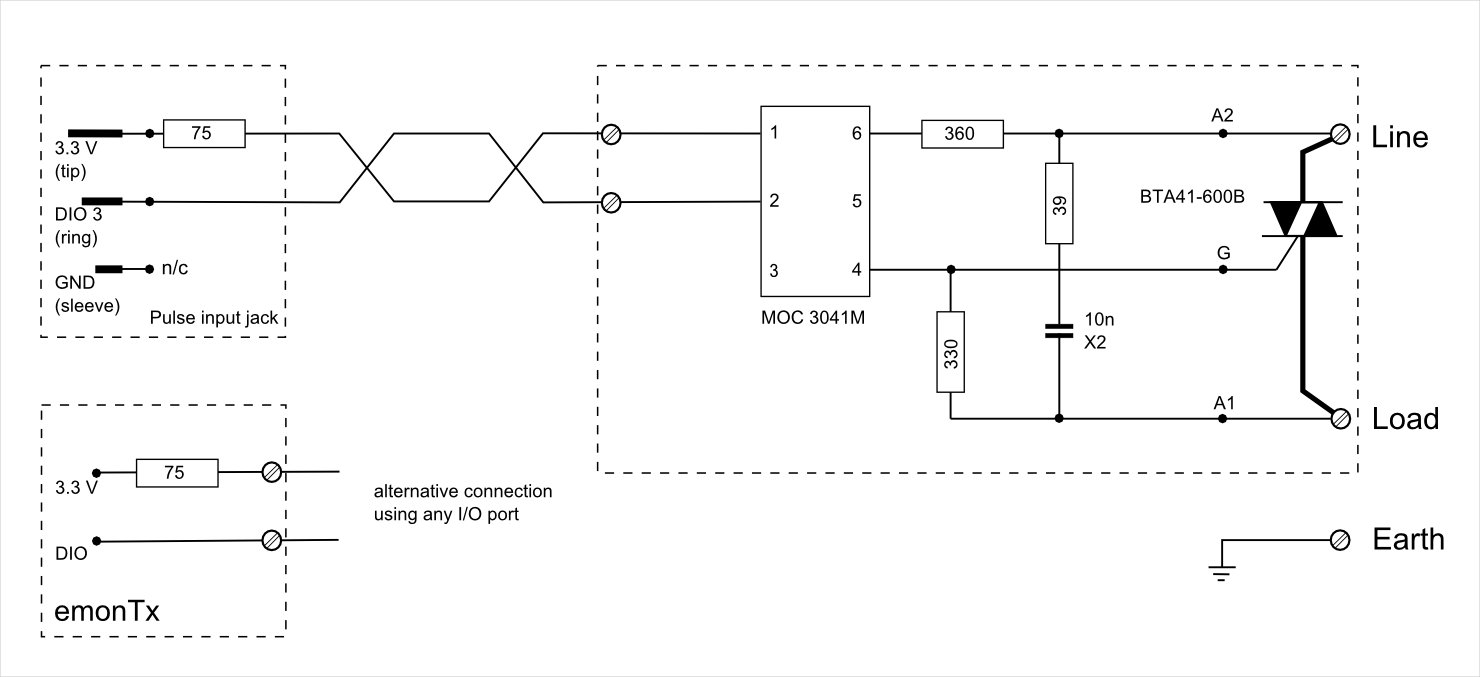
The output stage hardware
If it is not convenient to route the power wiring close to the measurement point, it is easy to separate the controller from the triac assembly. A simple low voltage twisted pair (‘telephone’ or CAT5) cable is all that is required to link the two parts, and it should be good for many tens of meters. If the two parts are in the same enclosure, the current limiting resistor may be more conveniently located on the output circuit board, as shown for the emonTx V3.
Output stage circuit diagram for emonTx V3. The differences between this and the emonTx V2 are explained in the overview.
The pcb for the output components mentioned above may be used with both the Arduino Uno and emonTx variants, and is available separately. Details can be found at http://openenergymonitor.org/emon/node/2044.
Alternatively, ‘Stripboard’ is the favoured method for many home construction projects.
For more detail: Diverting surplus PV Power