In semiconductor and electronics industry, a diode is a widely used discrete component. It is a significant element in many electronic circuits and applications ranging from low power signal circuits to power rectification. Based on the functions and ratings, there are different types of diodes. However, all semiconductor diodes contain a PN junction to perform their basic operation.
Definition of a Diode
A diode is a non-linear semiconductor device with two terminals that allows the flow of current in one direction. The two terminals of a diode are cathode (negative) and anode (positive).
Symbol of a Diode
Construction of a Diode
The layers of doped semiconductor materials form a PN junction diode. Doping is a process of adding impurities to lower the resistivity of the semiconductor. The N type material has excess electrons as majority carriers, while P type material has holes (positive charge carriers). The P type material and N type material combine to form a PN junction that is a thin layer between the two opposite majority charge carriers.
Construction of a PN Junction Diode
Operation and IV Characteristics
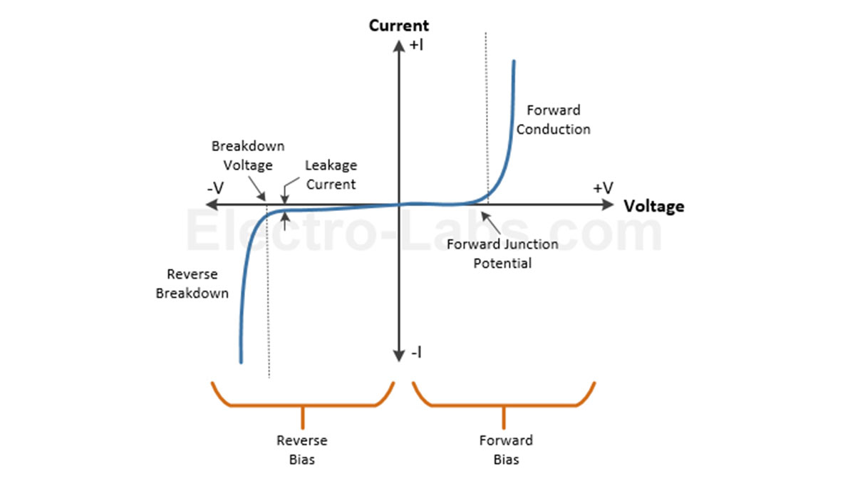
The current in a diode flows from anode to cathode in one direction. The relationship between the voltages and currents associated with the diode terminals is known as the characteristic curve. This curve describes the operation of a diode or its biasing conditions and they are as follows:
• Forward Bias – When the anode or P-type material is connected to a higher voltage than the cathode or N-type material, then the width of PN junction decreases and current flows from anode to cathode.
• Reverse Bias – When the cathode or N-type material is connected to a higher voltage than the anode or P-type material, then the width of PN junction increases and diode will not conduct electricity.
The formula expressing the relationship of current and voltage of a diode is as follows:
Is = reverse saturation current (typically < µA)
k = Boltzmann’s constant,
e = electron charge,
T = temperature,
Characteristic Curve of PN junction Diode
Applications of Diodes in Circuits
A variety of diode applications include protection of circuits by limiting the voltage with clipping and clamping, voltage multiplication i.e. doubling or tripling the input voltage, turning AC to DC with rectifier circuits, and amplitude modulation i.e. non-linear mixing of two voltages.
Switching
A diode is used in a variety of switching applications to modify the input waveform or protect circuits from excess voltage. Some of the switching applications are as follows:
Clipping or Limiting
The function of the diode in a clipping circuit is to cut off or limit part of an input signal. A simple clipper circuit consists of a diode and a resistor that clips a part of input waveform without distorting the remaining applied signal. The clipper circuit, input and output waveforms are shown below:
A Diode Clipper Circuit with Input and Output Signal Waveforms
Clamping
A diode is used in clamping circuits to change the DC value of a signal by charging a capacitor with the appropriate value. It will provide the desired DC level when connected with a voltage source in series.
Diode Clamping Circuit with Input and Output Signal Waveforms
Rectification
The most significant application of diode is in rectifier circuits that convert AC voltage to DC voltage. Diodes are used individually or in combination with different arrangements to make a variety of rectifier circuits including half-wave, full-wave and bridge.
Half-Wave Rectifier
A half-wave rectifier consists of a single diode connected with a voltage source. A resistor is connected as a load. The diode conducts only when the voltage at anode is higher than cathode, thereby allowing only positive voltages and rejecting negative voltages.
Half-wave Rectifier with Input and Output Signal Waveform
Full-Wave Rectifier
∴ Center Tapped Transformer Configuration
Center tapped transformer based full-wave rectifier consists of two diodes connected with a center-tapped transformer and it uses both halves of the input sine wave. When the polarity of voltage source is positive on the top and negative at the bottom, the top diode is conducting and the bottom diode blocks the current. In the next cycle, the voltage polarity reverses and bottom diode starts to conduct while top diode blocks current.
Center Tapped Transformer Full-wave Rectifier with Input and Output Signal Waveforms
∴ Bridge Rectifier Configuration
Another arrangement of diodes in full wave rectifier circuits is in the form of a bridge with four diodes. Two diodes conduct for positive cycles, while the other two conducts for negative half cycles.
Bridge Rectifier Circuit with Input and Output Signal
Freewheeling / Protection
Another common application of diodes is circuit protection from high inductive loads and reverse battery damage. Such a diode is connected in parallel with an inductive load or coil and is known as a freewheeling diode. When a switching device turns ON, the diode becomes reverse biased blocking the current. Conversely, when the device turns OFF, the energy stored in the coil causes the current to flow through the forward biased diode. This protects the circuit from high voltage spikes.
For more detail: Diodes – Types and Applications
