Step 1: Operation and Electronics Intro
How Does A Boost Converter Work?
Basic Principal:
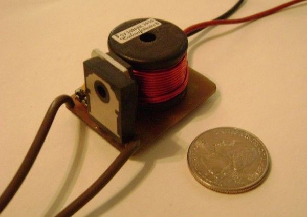
A boost converter works in two stages, ON and OFF. In the ON stage the Semi-conductive Switch is conducting and current builds up in the inductor producing an
electromagnetic field, this field stores energy. In the OFF stage the Semi-conductive Switch does not conduct and the electromagnetic field collapses. When the field collapses the energy stored
in it can not escape through the Semi-conductive Switch so it goes through the diode and into the load/Capacitor at a much higher voltage. This happens several
thousand times a second via the pulses from the NE555 Timer Chip and the result is being able to charge a high voltage capacitor from a low voltage source.
Below is some aid for those of you who do not know electronics well.
R-Resistor
VR-Variable Resistor (also called a Potentiometer)
B-Battery
V-Voltage Source
C-Capacitor
D-Diode
L-Inductor
U / IC-Integrated Circuit
Q-Transistor / IGBT
M-MOSFET
GND- Ground (Negative terminal of Battery for Portable Applications)
Some Diagrams and Charts are shown below to help you further.

Step 2: Protoboard Boost Converter 500V
This Boost converter is for those just starting out in electronics, do not have the materials to make a custom printed circuit board, or would like to spend less money on this project.
If you have the resources I strongly suggest the you make the Printed circuit Board Version of this device because it is simpler, smaller, and less likely to fail.
For more detail: DC-DC HV Boost Converter
