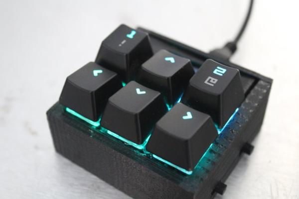
In this Instructable I will be taking you through the basics of creating your own 6 keyed macropad, controlled by an Arduino. I will be taking you through what you need, how to assemble it, how to program it, and how to improve it or make it your own.
After much research, I couldn’t really find a great guide on how to make a macro keypad, or a hand wired keyboard in general. So I decided to do it myself, in the simplest way possible, without diodes, resistors, or anything else. I also wanted to have a unique modular keyboard, where I could grab any parts that I needed, this is the first of many other parts. This module’s inspiration was from arrow keys on a keyboard, being able to fit it in your pocket, and taking it anywhere if you needed a few extra buttons on the go.
Due to how this keypad was made, I highly recommend that you read all of the Instructable before you make any purchasing decisions.
I also tried to make the Instructable in a logical order, but I don’t build logically, so it might be better to skip around in the order of the steps depending on how you build.
Step 1: Getting the Parts
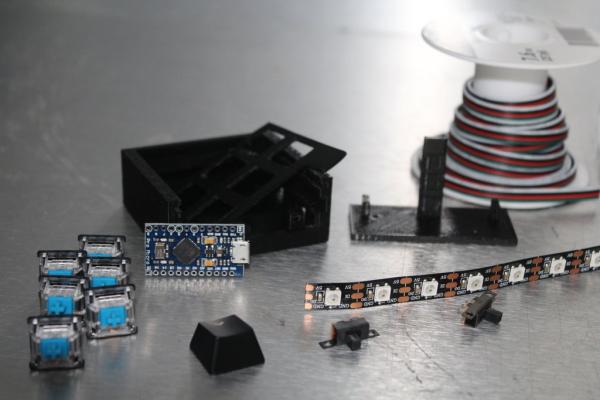
The longest step is right here, buying the parts and waiting for them to ship. Amazon links will be Canadian Amazon. The parts that you are going to need are:
- Mechanical Key switches
- I choose the Gateron switches with clear tops from here (Clear tops make the next step easier, most common types of switches are covered there too)
- Other places to buy can be found here under your favorite switch section
- I also highly recommend doing some research here on what switch you would like here under the ‘Feels’ section
- Mechanical Keycaps
- Make sure that they are compatible with your switch that you choose!
- Also make sure that they are back light compatible so you can change the colour
- Vendors can be found here under the ‘Novelty Keys (standard manufacturing)’ section, unless you want a full Keycap set
- Make sure that they are compatible with your switch that you choose!
- Addressable RGB LED strips (Optional, but highly recommended)
- I bought something similar to these from Amazon
- Make sure that the LEDs are WS2812B LEDs, they can accept a lower voltage.
- You could also buy 3mm regular LEDs of your favorite colour to use, but you’d need resistors
- I bought something similar to these from Amazon
- An HID compatible micro controller (I used a Pro Micro)
- I bought these from Amazon for the best deal
- You can buy other micro controllers, but make sure that they are both Arduino and HID (human input device) compatible
- I bought these from Amazon for the best deal
- A 128×32 I2C OLED display
- I bought this from Amazon
- Access to a 3D printer
- Try with local libraries or schools around you and see if they have a 3D printer
- I’ve personally never used an online service, but you could use those too (something like this)
- Thin Wire
- General Tools Needed
- Soldering Iron and Solder
- Side Cutter Pliers
- Small Files (Somewhat optional)
- Hot Glue Gun and Glue
- Screwdriver and screws of your choice
Step 2: Keyswitch Modifications
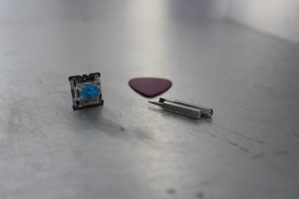
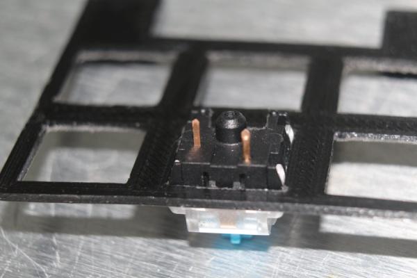
Start to disassemble the switches that you bought. We are doing this to allow the light to shine through better to reach our keycaps. If you have chosen keycaps that don’t support RGB, skip this step.
Take 2 small wedges (I used 2 flathead screwdriver bits) and push under the tabs on the side of the switch. Then put something in between the top and bottom so it doesn’t close. Proceed to push the tabs of the other side, so no tabs should still be holding the top on. After that, finish up and pop off the top of the switch. There usually is four parts, the top and bottom of the casing, the spring, and the stem (sliding part of the switch that holds the keycap).
Start to cut small little pieces out of the bottom of the case to allow more light to pass. Cut the tab that holds the switch on the plate first. Then cut a bit of the original LED pass through, (the part with the 4 holes, those are for the legs of the LEDs). Slowly cut down on that tab inside to get down to the bottom. Then proceed to cut up to the cylindrical center of the switch that holds the spring. We don’t need to go further than that. After that, widen the hole a bit, by slowly cutting off both sides with the pre-molded supports. Another optional step is to file it down, to make it nicer, and less jagged. Make sure that there are little to none plastic bits inside of the casing from this, as you don’t want the switch to get stuck. Make sure to do these cuts slow and small, as I’ve broken a few cases from the width of the side cutters forcing the case apart.
If the top half of your switch isn’t clear as well, try to modify it to allow the light to shine through. Try little by little without breaking the switch, because you don’t want the stem to fall out. A possible solution may be to cut out the piece of plastic that would hold a normal LED, and leave the plastic that keeps the stem enclosed, and only file it down.
Step 3: 3d Printing
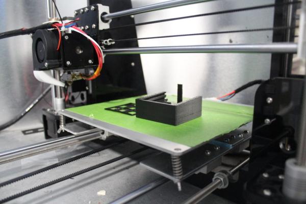
You will need to download one of the zip files below, and 3d print them. There will be different versions depending on what you want. There will be a folder with all of the normal stl files in it (KeybArrowSTLFiles), and one with the Autodesk inventor files (KeybArrowSourceFiles), so that you could modify the files and change them to your own needs. The files are slightly different from what I printed, this was because there were some design flaws, and I felt I could improve them. Example would be the sides of the case, mine were a bit too high so the keycaps wouldn’t push all the way down, the new files should fix that.
The design of them was pretty complicated, with over 30+ steps. All I will say is that if you want to design a case for a different size, you should make sure that you have experience with somewhat complicated 3d designs. It’s not really for people who are new to 3d design.
Step 4: Assembling What You Have So Far
Now that we have all of our parts, and we have the 3d printed parts, it’s time to assemble it a bit!
Place all 6 of the switches into the plate, and glue them in place. We need to glue them because we cut off the tabs that hold it in place. I suggest waiting to put in the OLED because you don’t want it slanted.
Next, cut 6 LEDs off and place them on the LED plate. The squares on the plate are to help you align the LEDs. The square LEDs will fit into them, so you could 3d print another to help alignment, or just line it from the back. Make sure that the arrows point to the other LEDs, as DO would be soldered to DI. Use those squares to glue on the LEDs with hot glue, and hold them in place and wait for the glue to hold.
I used a prototype plate for the switches to hold the LEDs (in the images) because I don’t like to waste filament, and decided to reuse. The new file won’t affect anything, just make it simpler to align.
Step 5: Setting Up the OLED
I recommend using this Instructable for a thorough walk through. They did a really well job of explaining it.
You will need to download and import this library and this library for the code to work.
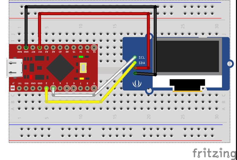
First wire it up. Wire VCC to VCC, and GND to GND. Then wire the SDA and SCL pins. The SDA and SCL pins may vary from each Arduino, but on the pro micro, SDA is wired up to pin 2, and SCL is wired up to pin 3. Look up a pinout of your micro controller if you are unsure of what pins SDA and SCL are wired to.
Next is to get it displaying and making images. There will be files below of how to get it working. The first step is to use the ScreenScan code (originally provided by Arduino here). Upload the code onto the Pro Micro and open the Serial reader (under the tools tab at the top). It will read you back and address of the OLED. If your address is 0x3C, then you don’t need to change anything. If it isn’t, then you need to go and change the address in the ssd1306_128x32_i2c code and the final code (named ArrowKeypad) so that it works properly.
Now test out the example code that was included with the Adafruit ssd1306 library that for the 128×32 i2c code (named ssd1306_128x32_i2c)
After that, keep the Arduino on, and try to line up the OLED on the switch plate, then turn it off and try to glue it in place. You will most likely not get this first try, but keep adjusting to try to get it aligned, so that it isn’t angled when it is completed. I suggest gluing one side a bit, and checking before you glue the other side to make sure that it isn’t slanted.
Step 6: Soldering
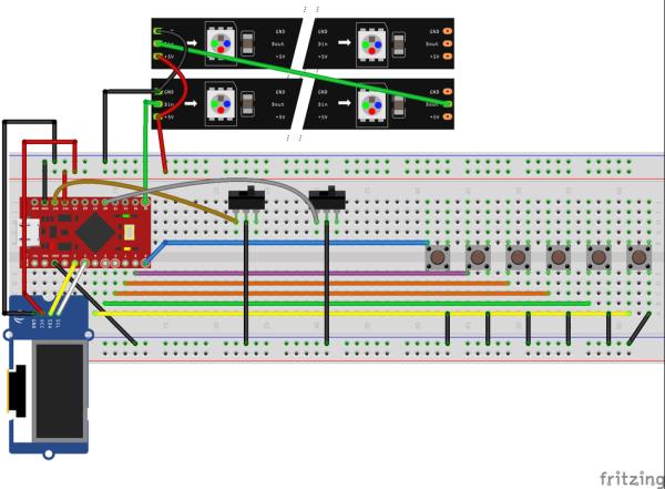
A Fritzing file will be available below. This will allow you to interact with the circuitry and if you left click and hold, you can see what wires are all connected (highlighted in yellow dots) files that need to be imported to Fritzing before you open the file will be down below (for the Pro Micro and LEDs).
Make sure the pins labled “MOSI, MISO or SCLK” are UNUSED or it will cause glitches with the OLED.
After cutting the 6 LEDs into single strips, and gluing them onto the plate. Place the soldering iron on the copper pads, and add solder to each of the pads. Cut small pieces of wire and strip half of it, twist it, then take the other half off and twist the wire. The wire will need to be held with pliers or some soldering helping hands, while you get it held in place by the solder. Add more solder to hold it there nicely. Solder all of the LEDs in the row together. Cut a wire, and solder it to the end of the LED on the first row, with the label ‘DO’ or ‘D-‘, and connect it to the first LED on the second row with the label ‘DI’ or ‘D+’. You can do this with the 5v and GND too, but it’s easier if the first LEDs 5v and GND on each row are wired together. Wire the 5v wire to VCC, Data pin to any digital pin (code has it set as 10) and GND to a GND on the Arduino.
To get the Arduino to recognize an input, the switches need to connect ground to a data pin. So, you can solder one wire to connect all 6 switches to ground. Solder one wire to each switch, and if possible, try to change the colours of wire to keep track of what switch is what wire. Feed the wires through the LED plate and wire them to a data pin on the Arduino (I used data pins 5-9 for this)
The two switches on the side have different functions, one is a reset switch for programming, while the other is a function switch, which will switch between layers of the Keypad to quickly change functions of the buttons. The top switch, is wired to reset (RST) and GND, when connected, it causes the reset. The bottom switch is wired up to pin 18, which is labeled as A0 on the Pro Micro.Give yourself some slack with the switch wires, as you still need to slide in the plates, and too little of a wire won’t allow the plates to inset through the top.
Source: Custom Macro Mechanical Keypad