I love this concept very much because kids like it very much. Now a days kids are always in mobile for study then for play and then for entertainment. Already i develop few projects with lights with arduino and Android. When i see through net i found this project is very interesting. I thank Mr.Taras Sgibnev, i see his model in web. It also teach kids the result of color mixing and make them happy. When you see you think its very simple to build, but it is little difficult to make it. I plan to make as a night lamp for our room. So with out using cardboard i use durable materials and also power supply directly given from EB supply.
After completion Its very big in size 2.5 feet height and nearly 1 feet X 1 feet square. Its a jumbo light.
Step 1: Materials Required
Materials Required
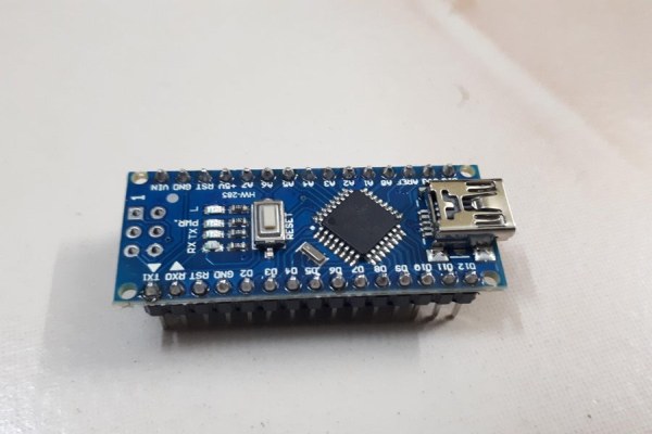
1) Arduino Nano – 1No.
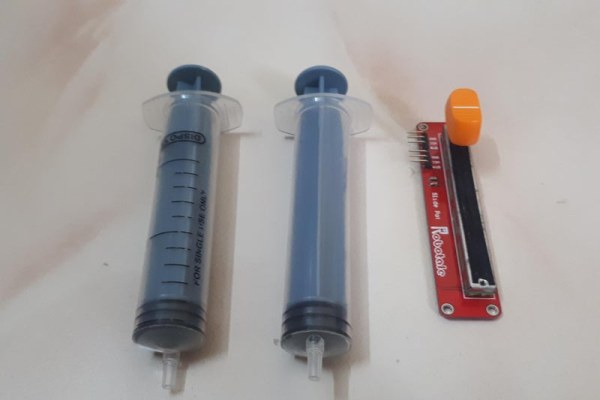
2) Sliding variable Resistor – 3Nos.
3) Addressable RGB LED – 1 Strip (60 nos led).
4) 230V AC to 12V DC SMPS.
5) LM2596 DC to DC adjustable step down module.
6) 200ml Syringe – 6 Nos.
7) Plain PCB, Male and female header pins, Ribbon Wires etc.
8) 75mm PVC pipes – 690mm length .
9) 3mm Sun Shade sheet.
10) 8mm wooden board – 2 feet X 2 feet.
11) 4mm fish tank air hose – 3meters
12) Feviquick.
13) Wooden Sticks.
14) Wooden boards.
15) Food Colors (Red, Blue and Green)
Step 2: Circuit Plan
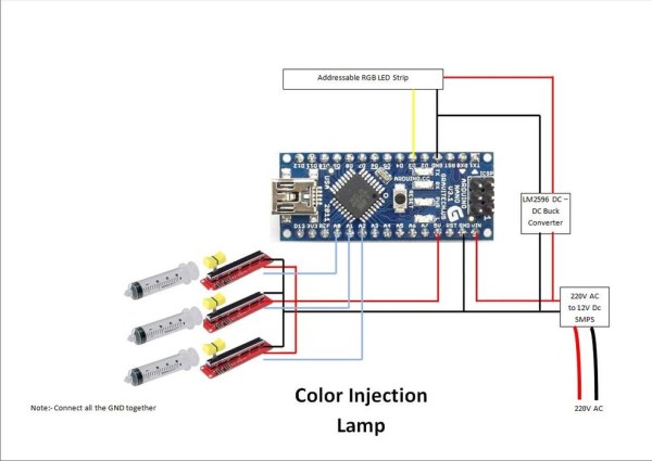
The Circuit plan is very simple and basic. 3 sliding variable resistor output connected with the analog pins A0, A1 and A2. Addressable led string data pin connected to D3 of arduino. Arduino Vin and gnd connected directly from 12V Smps output. Adddressable LED strip vcc and Ground to LM2596 output and LM2596 input connected to 12V smps supply.
Step 3: Make Shield
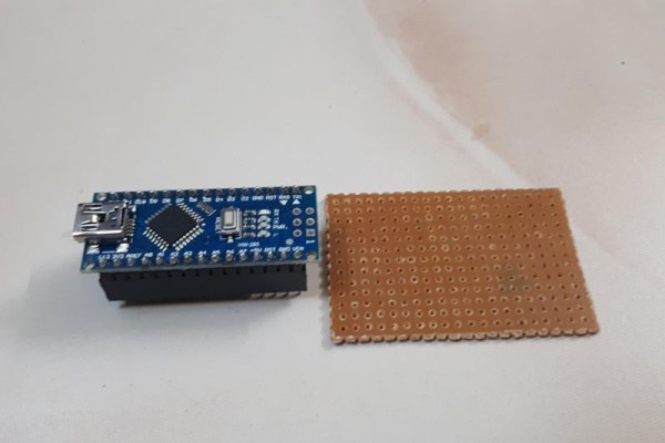
Every time i make a shield for each project and so i have a box full of shields. As per circuit plan i make a shield using plan board. I plan to connect the wires using male and female header pins, because while assemble the lamp we want to remove the wires and pass through holes. As per circuit pins with supply must be female connector, So Power supply input pin in arduino side must be male header and all other pins are out put from arduino so all other pins must be female connector.
Step 4: Cables Preparation
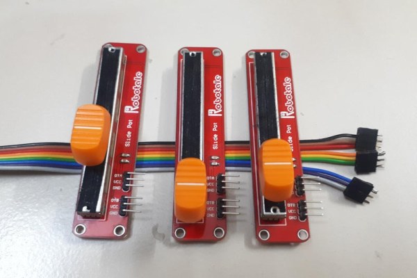
From arduino to Sliding resistor, i use long 9 color ribbon wire. Divide wires in to 3 sets and solder male header one side and female header on the other end.
Step 5: Power Supply Arrangement
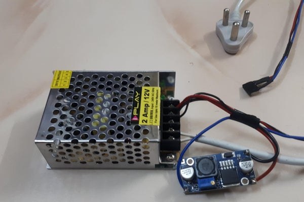
I plan it to hang on the roof of the room. In the roof supply available is 230V dc from switch, So i use 230v to 12V dc converter. Don’t connect the led strip power to arduino 5V because it may damage the arduino. So i use LM2596 to convert 12 V to 5V DC. Make a single female connector for the power out. And this is connected to the arduino male connector near the Vin side. Becareful while connect the header pin to arduino if reversed 12V send to LED strip cause LED strip failure..
Step 6: Careful With Power
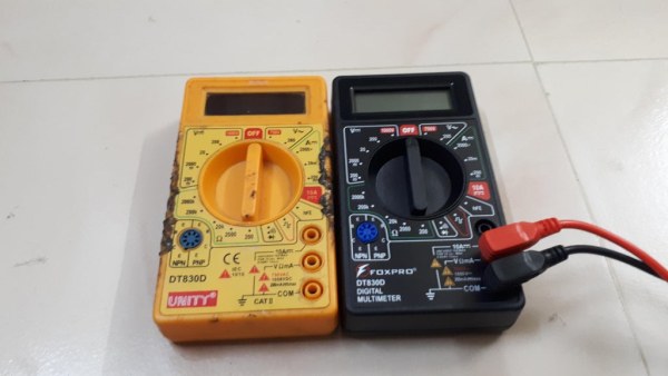
Be Careful while working with the high power supply. I lost my multimeter while working, the markings are dim in the yellow multimeter. I put the mode in resistor and check the 230 V AC supply, its burned. I use thgis multimeter for last 20 years. I miss this multimeter but God grace it never cause more problem. So be careful.
Step 7: Light Arrangement
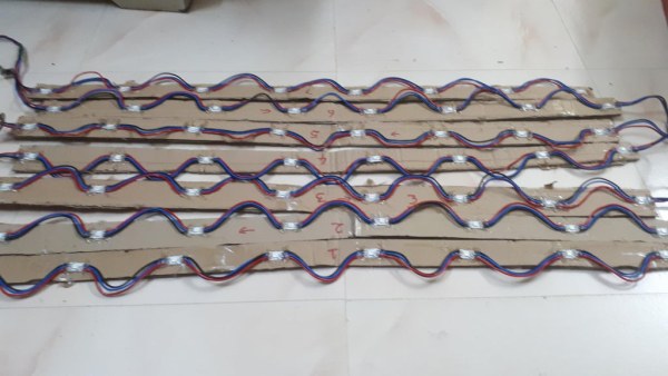
Actualy it is a 60 addressable RGB led. I use it for my previous project 7 Feet 7 Segment RGB Display With BT App. Due to space concern i remove the materials from that project and store it sperately. Now use that leds in this project.
Step 8: Arduino Program
This is a small Program. Use led PololuLedStrip library to drive the addressable led strip. Receive the analog signal from resistor in pis A0, A1 and A2 Use Map in arduino to convert the 0 to 1024 to 0 to 255 and check in each cycle if its differ from previous color then change the color of all leds’s in the strip.
Step 9: First Trial
First check the circuit with the code and adjust the potentiometer to generate all colors. See the video of its testing.
Step 10: Syringe Fix With Sliding Potentiometer
This one is one of the difficult task if you have 3D printer then its very simple but i use woods and materials available in my box.
1) Remove the knob of the sliding potentiometer.
2) Cut the plunger round piece in the back.
3) Cut the plunger in the center up to 2 cm.
4) Slider base is higher from the floor so cut novopan sheets and stick with the base of the syringe using feviquick (qucik fixing gum). Don’t use hot glue gun in the syringe side, because it cause syringe melt.
5) Screw sliding resistor in a straight stick with around 25cm between each sliding resistor.
6) Insert the 2Cm cut portion of the syringe plunger to the sliding resistor knob and hot glue it.
7) Arrange the syring straight with the sliding resistor and use hot glue gun stick it with the base stick.
Step 11: Testing the Syringe
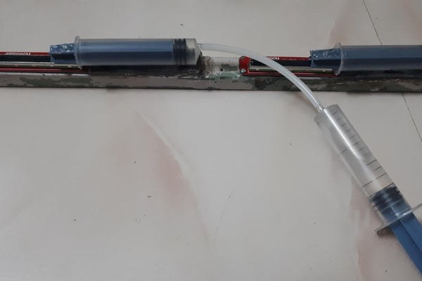
Test all the three syringe fixed with the varaible resistor with another syringe.
Step 12: Arrange Leds in a Round Pipe
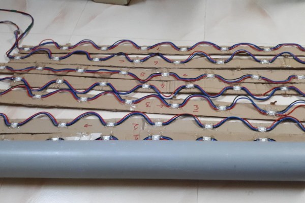
1) I choose a 75mm pipe for led Arrangement. I found the LED strinp length is very high so first cut the pipe for 670mm height. At first the strip length is around 820mm (its made for my previoud project) change the strip length to 670 mm by cut the space between each led’s and strick with tape.
2) Arrange the Leds around the pipe and Tie any three places using white twine rope. I have 7 strips used in 7 segment display but i able to arrange only 6 strips so remove the 7th strip.
3) Then move the strip and arrange in equal spacing.
4) using hot flue gun stick the strip with the pipe.
5) Then use the twine rope tie the wires with the pipe to avoid wires pop out. Now the Strip is ready and want to test.
Step 13: Test the Arrangement
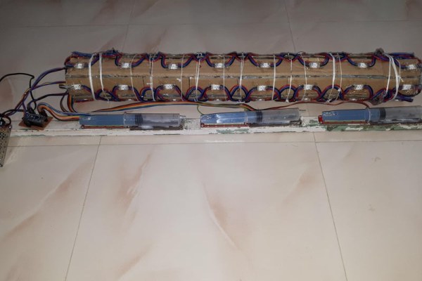
Connect the Arduino, Potentiometer Syringe and power supply to the strip. And check all the leds are glow. On my checking after 2 and strip in third strip only one led glow after that all the leds are not glow, check and found the Led output dc voltage to next led is broken, resolder and found in the 5 the strip after 4 the LED all leds only burn in white color. Check and found in the 4 th led output Data pin broken, resolder it and found all ok. Change the syringe length and test the colors.
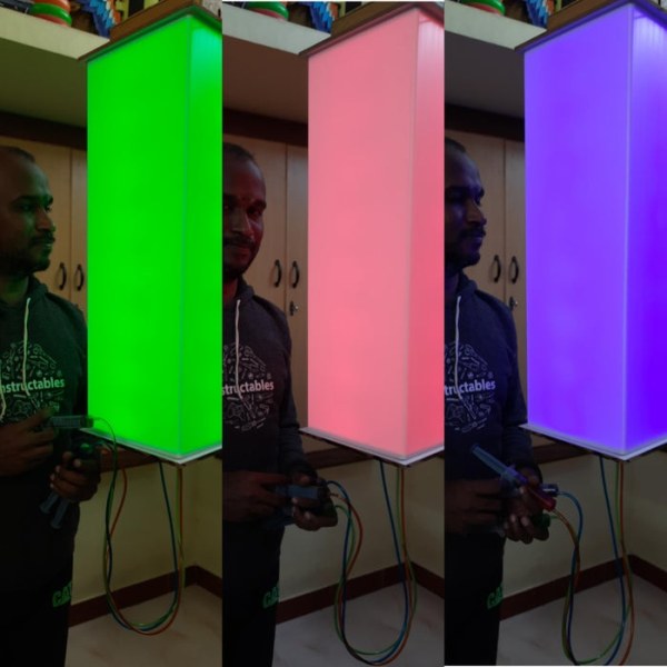
Step 14: Some Selfie
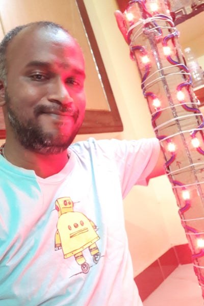
After hard work up to 2 am its some satisfaction on the result how it glow so remember that movement a selfie.
Step 15: Make Shade
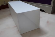
1) For 3d printing this size almost 690 mm height shade is very very costly. so i search for low cost but same result shade. I check with thermocol sheet, Cloth and finally 3mm sun shade its result is amazing. 3mm white pvc sun shade sheet 6feet X 4feet is only 150Rupees (2 Dollars).
2) The height we want to take is 690mm + 8mm + 8mm (i have 8mm wood sheet for hold the shade so for both side 8 + 8). I take 706mm height.
3) First cut height the and check with the light how much distance give nice result. When very close light dots are shown so check with each distance and found almost 65 to 75 cm from the light it shows the nice glow. So the square we want to cut is 80 cm for the light + 70 + 70 (for both sides) = 220mm.
4) So impress the sheet with thick screw driver in each 220mm (carefully impress straight line)
5) Take four part and cut the lost.
6) Paste the edge with feviquick (quick fixing solution).
7) Now the lamp shade is ready.
Source: Color Injection Lamp – Jumbo Size