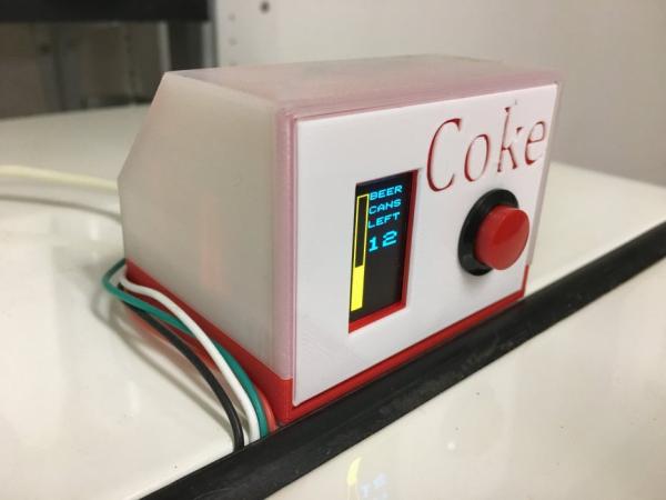
Rev 2.5 – tidied up the 3D printed parts and updated the plug connector to a common PCB unit.
Rev 2 – ultrasonic “button” replaces manual push-button.
Pushing a button is so old fashion, particularly when I’m already using an Ultrasonic sensor. Why not use an ultrasonic sensor to activate the can level detector! Rev 2 removes the push-button and replaces it with another HC-SR04 module. Now, just walk up to the machine and it turns on automatically to reveal the can level. I lost the “Coke” logo in the process, but I only had to change the faceplate – all other printed components remain the same.
I’m fortunate enough to have an old Coke machine that I use for, er, “refreshments”. It holds about 30ish cans when full. The trouble is, how many cans are in it at any given time? When do I need to make a run to replenish the machine?
A solution (apart from opening the machine all the time) is to whip up a sensor, or “can level detector” that can approximate the number of cans in the machine at any given time. I decide that it had to meet the following requirements:
– must be cheap and simple
– non invasive (I don’t want to start drilling or cutting into my machine)
– Use Arduino Nano
– Use an LCD screen to give me easy-to-understand readings
– be powered by the native USB or an external power supply
– use a momentary push-button for “as-needed” readings (now using 2nd HC-SR04 module instead).
I had some ultrasonic modules, some Nanos, and a tiny LCD screen and decided that they might come in handy here.
After a bit of searching, I had all the necessary elements (hardware and coding) to make this work. The only outstanding question was – would the ultrasonic sensor be able to register a meaningful distance by bouncing the signal off of cylindrical cans?? It turns out that it in fact “can”! (sorry for the pun).
Step 1: Hardware

Ok, this one is pretty straightforward.
– Arduino Nano
– Kuman 0.96 Inch 4-pin Yellow Blue IIC OLED (SSD 1306 or similar).
– HC-SR04 ultrasonic ranging modules (qty: 2 for automatic version)
– Generic SP pushbutton if not using 2nd HC-SR04 module (optional)
– female plug receptacle for 7-12V wall adapter (optional)
– approx 14″ of 2-pair phone jack cable for more elegant external wiring
Step 2: 3D Printed Case

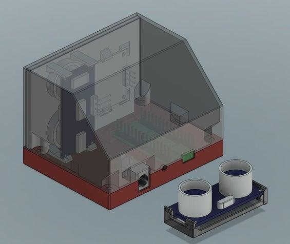
A total of 4 printed parts are used in this build:
– Bottom (red)
– Translucent top
– Slide in front panel (red and white colour print)
– Ultrasonic sensor holder
The parts are designed to be printed without supports using Fusion 360.
No fasteners are needed for assembly; all parts snap together! The top can be removed after assembly by slightly squeezing either side of the top near the base and pulling the top off.
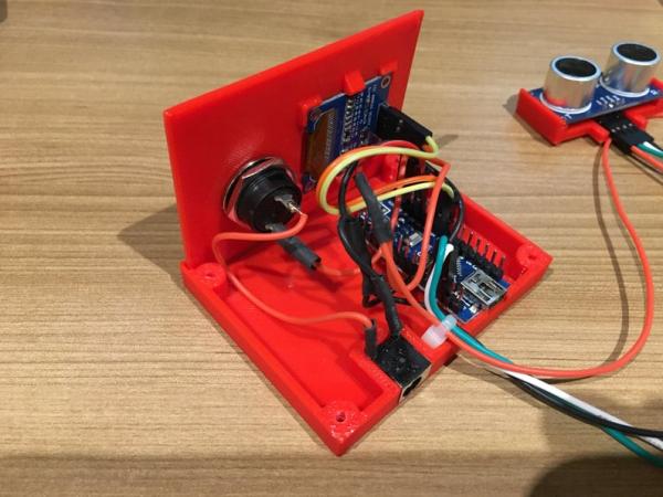
The LCD screen snaps into the cover. The base has a receiver slot at one end and a saddle at the back for the Nano, locking the board in the base. The 12V plug adapter is now a common PCB mount unit I get in bulk for about a quarter and the top holds it in place. The front face slides into receiver grooves in the top and bottom elements.
The parts are all PLA, with the top being translucent so I can see the box glow when turned on!
To provide the red accents on the front cover, I print the white portion shown at 0.08mm thick (.02 layer thickness) and red for the remainder, which looks clean.
Step 3: Wiring

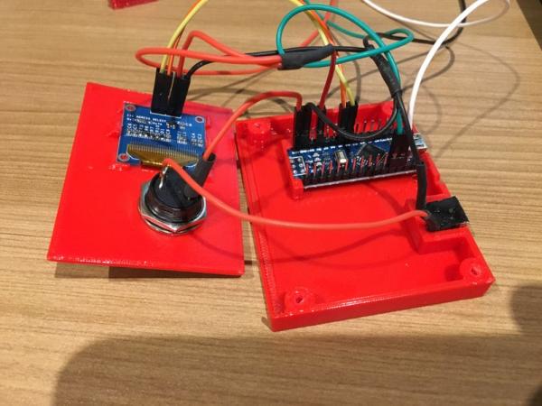
The wiring for this project is pretty simple. 5V power and ground to the LCD screen and the ultrasonic modules from the Nano. A pair of signal wires from the Nano to the LCD, and two pairs from the Nano to the ultrasonic modules. A few extra leads for the optional 12V feed and voila!
In my first build, I had a Nano with pins installed, so I decided to use it as-is and make up some prototype wiring to suit. The stupid little connectors are always a bit finicky to make up, in my opinion, but then again, there weren’t too many. One could always forgo these connectors and solder the whole thing up. Maybe next time…
On subsequent builds, I only install header pins in the Nano for the connections I actually use. Makes it easier to install cables and avoid mistakes.
I also used a 2-pair common phone cable to make the lead to the can sensor in the machine. It provides for a nice, clean cable that is affordable (free, and all over the place nowadays!)
Step 4: Code
The code is cobbled together from various sources (as is most project coding).
I started with the ultrasonic sample from Dejan Nedelkovski at www.HowToMechatronics.com. Good tutorial.
I then pulled some LCD code from Jean0x7BE at Instructables.com and learned some more from a bunch of other sites. I followed his instructions there, and added both required libraries:
https://github.com/adafruit/Adafruit_SSD1306 (SSD1306 library)
https://github.com/adafruit/Adafruit-GFX-Library (GFX library)
I also went through the example files in the SSD1306 library and learned from that.
In the end, the code is kludged together from these sources and with some tinkering, it gave me the the result I was looking for.
The design now incorporates a second ultrasonic module for a walk-up sensor. Stand in front of the device and the screen turns on, walk away and it turns off after a few seconds. Comment out the person sensor if on all the time or if push button option is used.
Source: Coke Machine Can Level Detector
