Summary of Build an Arduino-powered talking robot head using arduino
This article details the construction of a DIY talking robot head for a physical computing class. The project uses two microcontrollers, LED matrices for eyes and mouth, servos for eyebrows, and an audio shield to simulate speech and emotions. It serves as a foundation for future internet-connected applications like email reading.
Parts used in the Talking Robot Head:
- Breadboard (48+ rows with center gap)
- 2 RGB LEDs (Common Anode)
- 36 Red LEDs
- 2 HXT900 Micro Servos
- 3 TLC5940NT chips
- 3 Capacitors (~1000uf)
- 2 Freeduinos or Arduinos
- Adafruit Waveshield
- Cardboard box
- Small block of wood
- Heat Shrink tubing
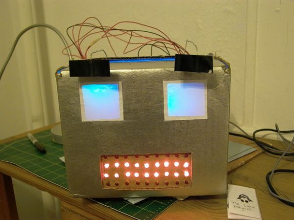
This robot head was originally built as a end of the year project for my physical computing class, but over the summer it has “learned” how to talk.
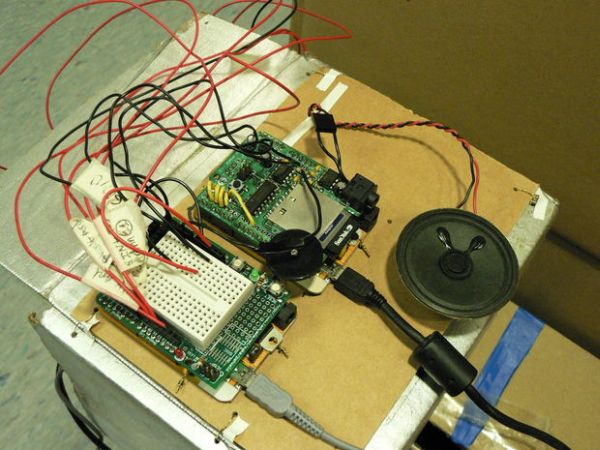
The head is powered by two Freeduinos, 3 TLC5940NT chips and an Adafruit Industries Wave Shield found here: www.ladyada.net/make/waveshield/. The head is currently connected to a computer by two USB cables, one for power, one for sending it serial commands on what to say/emote. Once the head receives the typed commands on what to say/emote it plays back the individual word files in order creating a sentence or multiple sentences. It also changes its emotions according to the emotional commands sent from the computer.
This robot head is a foundation for many possible applications since it can say anything that it has the vocabulary for. Right now I am currently working on connecting it to the internet and making it check and read my email via PHP script. I will update this Instructable as I progress along with that.
The head is still an on-going project so any comments on anything here are more than welcome!
Special thanks to Liz Arum for helping me with everything!
Update: Due to popular request I now have now added a video of the robot talking and expressing itself! Enjoy at your leisure!
Step 1: Compile all materials/parts/electronics.
1 Breadboard (It has to be more than 48 rows long with a gap running down the center of the board to connect IC chips. A power and ground bus running along the side of the breadboard is also a necessity.)
2 RGB Leds (For the multicolored eyes) Common Anode. $1.50 – 1.95 each. 2 X $1.75 = $3.50
36 Red Leds (For the mouth) somewhere around the 40-50 cent price range for each. 36 X $.45 = $16.20
2 HXT900 Micro Servos (For moving the eyebrows) Can be found at: http://www.hobbycity.com/hobbycity/store/uh_viewItem.asp?idProduct=662 2 X $3.65 = $7.30
3 TLC5940NT’s (To drive/light up all the Leds and control the servos) can be found at Digi-key http://search.digikey.com/scripts/DkSearch/dksus.dll?Detail&name=296-17732-5-ND where they are priced at $4.28. 3 X $4.28 = $12.84
3 Capacitors (~1000uf) (for ironing out line noise from the Leds and servos) Salvaged from an old computer power supply. Free
2 Original Freeduinos or Arduinos. The Freeduinos can be bought at http://www.freeduino.org/buy.html They are priced at 23.99 each. 2 X $23.99 = $47.98
Or www.sparkfun.com/commerce/product_info.php for Arduinos. Priced at $29.95 each. 2 X $29.95 = $59.90.
Warning: The Freeduinos require some soldering knowledge, if you would like not to solder your boards then buy an Arduino.
Warning: This Instructable requires some soldering knowledge anyway, so why not start now? 🙂
1 Waveshield from Adafruit Industries (To allow the robot to talk) Can be bought at: http://www.ladyada.net/make/waveshield/ Priced at $22 each.
Estimated total cost of all high tech parts(not including shipping) if you bought Freeduinos instead of Arduinos is…. $109.82!
The total cost of all high tech parts if you bought Arduinos instead of Freeduinos is…. $121.74!
And as for the low-tech materials you will need:
A cardboard box the same size that you want your head to be.
A small piece of cardboard
Tape
Glue
Breadboard compatible wire (22 gauge, solid)
Wire for fastening stuff to other stuff
A small block of wood
Power drill.
Heat Shrink tubing for isolating the exposed wire leads and something that blows hot air to shrink it with (Hot air gun)
Box cutter.
Step 2: Assemble and solder all circuitboards and shields.
Solder the Freeduinos (like I did), Or disregard this line if you bought a Arduino. Here is the link to their assembly instructions for all of the people who bought Freeduinos:
mcukits.com/2009/03/12/assembling-the-freeduino-board-kit/
Solder the Waveshields. Lady Ada has a very good guide on how to do this on her website at http://www.ladyada.net/make/waveshield/solder.html
Note:
In addition to soldering together the Waveshield as outlined. Add a long wire soldered onto the resistor R7 on the side closest to the amplifier chip. This will be connected to the Analog Input 1 on the Freeduino that is controlling the LEDs of the robot head. (Don’t worry about where to plug the other end of the wire for now, that will be explained in detail later.) See the picture for clarification on where to solder the wire.
Step 3: Design the robot head.
Take the cardboard box that you chose to be your head and mark out the places that you would like to cut out for the eyes and mouth by cutting pieces of paper and laying them on top of your box. When you are happy with the arrangement you can move onto cutting stuff.
Step 4: Design your Robot head: Cutting the eyes out.
Tape or mark the pieces to their final positions onto the box and cut them out. (Keep the piece of paper that you used to represent the mouth, you will need it later.)
Step 5: Design your robot head: Making a LED matrix for the mouth.
Each LED in the mouth will light up independently. To do that you need to make an LED matrix for the mouth. (For an idea on what is a LED matrix, see picture 1)
Take the piece of paper that is supposed to be the mouth and, with a pencil and ruler, Divide up the piece of paper into 36 parts (9 X 4), One for each LED in the grid.
After you have done that, tape the piece of paper to a piece of wood and being careful not to drill through the floor (This has happened to me so I recommend drilling on top of a cardboard box.) Drill holes where the lines intersect with a 1/4 inch drill bit, so that your LEDs fit snuggly. The size of the drill bit is obviously dependent on the size of your LEDs so use a smaller drill bit for smaller LEDs. (Start small and work your way up!) Look at pictures 2&3 for clarification on the drilling/marking.
Step 6: Making the mouth LED matrix: Soldering in the LEDs.
Before doing anything else, check that all your LEDs are not burned out or dim. You can do this by finding a small 3V button battery and holding the legs of the LEDs to the battery (Remember the long leg is positive, the short negative).
Next insert the LEDs one row at a time into your drilled out grid jig. Fold the long legs so that they are parallel to one another and solder them in, row by row (See pictures 2 & 3). Solder together the long legs since you will be using TLCs to control these LEDs, and the TLCs are power sinks. This means that they control the LEDs by altering the voltage differential between power and ground.
Step 7: Making the mouth LED matrix: Soldering control wires onto the LEDs.
Solder long wires that can fit into a breadboard (22 gauge) onto all the LED cathode leads. These wires will control the LEDs. Afterwards be sure to insulate all the individual wires with electrical tape(not fun) or heat shrink tubing(recommended).
In addition to soldering wires onto all of the LEDs Cathode leads, solder 2 or 3 wires onto the Anode part of the grid (The part that is all soldered together). These wires will serve as power supples distributing power all throughout the grid. They will be connected to 5V.
Step 8: Install the eyebrow-moving servos inside of the robot head.
Before installing your mini-servos inside of your robot head, hot glue a long strong (But still bendable) wire onto the servo arm. This wire will go up the inside of your robot, come out of the top and creep back down to move the eyebrows. (See the pictures for clarification.)
Take your mini-servos (with the wires attached) and hot glue them to the inside of your robot head, right underneath the eyes, making sure that the wires can move from side to side.
Step 9: Install the grid inside of the robot head.
Hot glue the grid to a piece of cardboard that you have drilled holes in and hot glue that onto the inside of the robot head.
Step 10: Solder the RGB LEDs.
Solder the Common Anode RGB LED lead to a long wire. Then solder a colored wire (red, green, blue) to the RGB LED lead that corresponds to it (The color of an individual lead can be found out by using a 3V button battery to light each LED lead in turn). Don’t forget to insulate the wires!
For more detail: Build an Arduino-powered talking robot head
- How does the robot head speak?
The head receives serial commands from a computer to play back individual word files in order to create sentences. - What components drive the LEDs and servos?
Three TLC5940NT chips are used to drive all the LEDs and control the servos. - Can I use Arduinos instead of Freeduinos?
Yes, you can use Arduinos, though they cost slightly more than Freeduinos. - How are the eyebrow movements created?
Two HXT900 Micro Servos are installed inside the head with wires attached to move the eyebrows. - What is required to build the mouth LED matrix?
You need 36 red LEDs, a piece of wood, and a drill to create a grid where each LED lights independently. - How do I power the LED grid?
Wires soldered to the Anode part of the grid distribute power from a 5V source throughout the grid. - Does the robot change expressions?
Yes, it changes its emotions according to emotional commands sent from the connected computer. - What future updates are planned for this project?
The author plans to connect the head to the internet to check and read emails via a PHP script. - Is soldering knowledge necessary for this project?
Yes, the Instructable requires soldering knowledge, especially if building Freeduino kits yourself. - How are the RGB eye LEDs identified?
You can identify the color leads by using a 3V button battery to light each LED lead in turn.