Summary of Build A Binary Clock Using Arduino
This project demonstrates a binary clock using an Arduino and a DS1307 Real-Time Clock (RTC) module. Sixteen LEDs display the time in binary format, with four LEDs representing hours, six for minutes, and six for seconds. The system utilizes two 74HC595 shift registers to manage the LED states efficiently.
Parts used in the Binary Clock:
- DS1307 Breakout Board & RTC
- 2 x 74HC595 Shift Registers
- 16 x LEDs
- 16 x 330 Ohm Resistors
- Jumper Wires
- 2 Full Size Breadboards
Introduction
In this project, 16 LEDs are used to represent the time in binary. The time is read from a Real Time Clock breakout board – the same one used in the Digital Clock page.
The binary clock uses 4 place values for the hour (12hr format), 6 place values for the minutes, and 6 for the seconds.
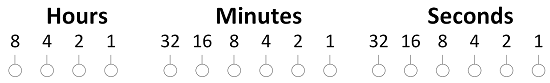
So the following pattern…
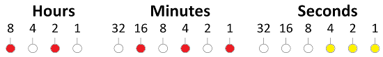
… makes the time, 8+2 = 10 hours, 16 + 4 + 1 = 21 minutes, 4+2+1 = 7 seconds.
You Will Need
- DS1307 Breakout Board & RTC
- 2 x 74HC595 Shift Registers
- 16 x LEDs
- 16 x 330 Ohm Resistors
- Jumper Wires
- 2 Full Size Breadboards
Making The Circuit
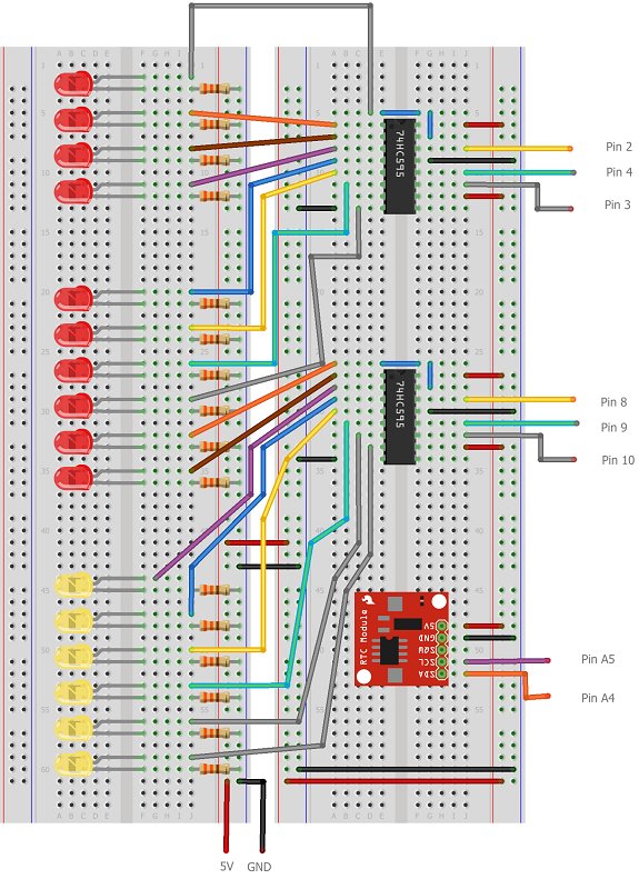
Take care with this one, there are a lot of things to get connected. The Arduino isn’t shown in this diagram. The text labels show the pin connections – the connections to the shift registers are to digital pins.
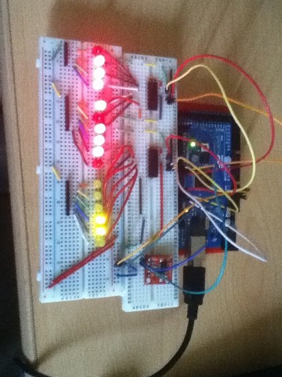
Here is a blurry photograph of the binary clock circuit set up on an Arduino Mega. There are some minor differences to the diagram to account for the differences between the Uno and the Mega. Some of the components (eg resistors) are also slightly different. However, it works just like the one in the diagram.
Programming The Arduino
The tricky part of this code is to create the correct binary pattern. The first shift register controls the 4 LEDs that make the hours as well as 4 of the LEDs that make up the minutes. The second shift register does the other 2 LEDs of the minutes as well as all of the seconds.
Because of the number of places where a faulty or missing connection can prevent this from working, it’s worth just checking that you can light all of the LEDs properly. With the rest of the code as below, replace the loop with the following lines to make sure that all of the LEDs can be lit,
  writeByte(255,1);

writeByte(255,2);
The main program,
#include <Wire.h>

#include "RTClib.h"
RTC_DS1307 RTC;
int datapin = 2;
int clockpin = 3;
int latchpin = 4;
int datapin2 = 8;
int clockpin2 = 9;
int latchpin2= 10;
void setup()
{
Serial.begin(57600);
Wire.begin();
RTC.begin();
if (! RTC.isrunning()) {
Serial.println(“RTC is NOT running!”);
// following line sets the RTC to the date & time this sketch was compiled
//RTC.adjust(DateTime(__DATE__, __TIME__));
}
pinMode(datapin, OUTPUT);
pinMode(clockpin, OUTPUT);
pinMode(latchpin, OUTPUT);
pinMode(datapin2, OUTPUT);
pinMode(clockpin2, OUTPUT);
pinMode(latchpin2, OUTPUT);
}
void loop()
{
DateTime now = RTC.now();
// All used for checking the time of the clock
// This section can be removed when everything is working
Serial.print(now.day(), DEC);
Serial.print(‘/’);
Serial.print(now.month(), DEC);
Serial.print(‘/’);
Serial.print(now.year(), DEC);
Serial.print(‘ ‘);
Serial.print(now.hour(), DEC);
Serial.print(‘:’);
Serial.print(now.minute(), DEC);
Serial.print(‘:’);
Serial.print(now.second(), DEC);
Serial.println();
// End of section that can be removed
int mins = now.minute();
int secs = now.second();
int hr = now.hour();
// convert to 12 hour time
if (hr>12)
{
hr = hr-12;
}
// variables to describe pattern of on lights
byte data1 = 0;
byte data2 = 0;
// encode the time
// hr = 1st four bits
for (int i =0;i<4;i++)
{
if (bitRead(hr,i)==1)
{
bitWrite(data1,3-i,1);
}
}
// mins on the first shift register
for (int i =2;i<6;i++)
{
if (bitRead(mins,i)==1)
{
bitWrite(data1,9-i,1);
}
}
// remaining mins LEDs
for (int i =0;i<2;i++)
{
if (bitRead(mins,i)==1)
{
bitWrite(data2,1-i,1);
}
}
// seconds
for (int i =2;i<8;i++)
{
if (bitRead(secs,i-2)==1)
{
bitWrite(data2,9-i,1);
}
}
// output the information
writeByte(data1,1);
writeByte(data2,2);
// a brief pause
delay(500);
}
void writeByte(byte data, byte set)
{
int d,c,l;
if (set==1)
{
d = 2;
c = 3;
l = 4;
}
else if (set==2)
{
d = 8;
c = 9;
l = 10;
}
shiftOut(d, c, MSBFIRST, data);
// toggle the latch pin so that the data appears as an output
digitalWrite(l, HIGH);
digitalWrite(l, LOW);
}
For more detail: Make A Binary Clock Using Arduino
-
How many LEDs are used to represent the time?
16 LEDs are used to represent the time in binary. -
What components are required to build this circuit?
You need a DS1307 Breakout Board, two 74HC595 Shift Registers, 16 LEDs, 16 resistors, jumper wires, and two breadboards. -
How is the time displayed on the LEDs?
The time is displayed using binary place values: 4 for hours, 6 for minutes, and 6 for seconds. -
Which library is included for the Real Time Clock?
The code includes the Wire.h and RTClib.h libraries to interface with the RTC. -
How does the code handle 12-hour time conversion?
The code checks if the hour is greater than 12 and subtracts 12 to convert it to 12-hour format. -
What pins control the first shift register?
Digital pins 2, 3, and 4 are used as data, clock, and latch pins for the first shift register. -
How can you verify all LEDs are working correctly?
Replace the loop with writeByte(255,1) and writeByte(255,2) to light all LEDs simultaneously. -
What happens if the RTC is not running?
The program prints RTC is NOT running! to the serial monitor but continues execution.