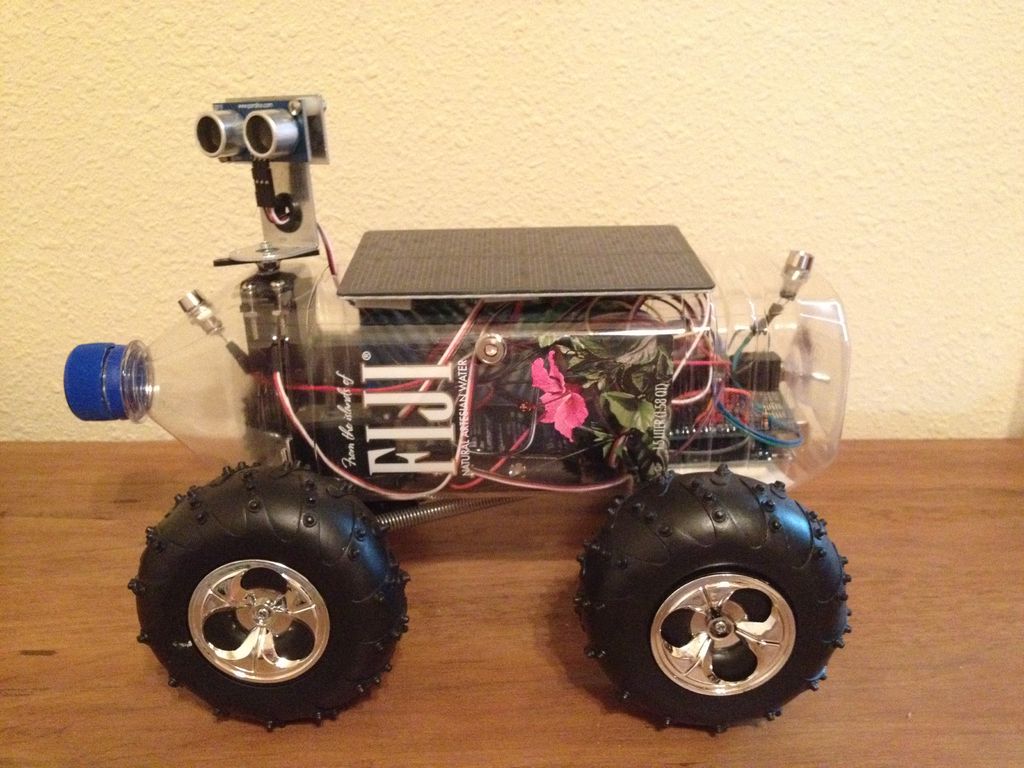
Fijibot is an autonomous, self-charging photovore. I built him using a 1.5 liter Fiji Water bottle, an Arduino Uno, 6v solar panel (plus various other parts) from Radio Shack, an Arduino Proto Shield (plus various other parts) from Adafruit, and the wheels and steering arrangement from an RC car.
I decided to use a Fiji Water bottle as the robot’s exoskeleton because Fiji Water is an environmentally conscious company and Fijibot recharges its batteries via a solar panel. Plus, I think the round-edged rectangular shape and the (see through) clear bottle make a really cool looking robot!
Step 1: Materials & Tools
Materials:
1 – 1.5 Liter Fiji Water Bottle (I actually used several bottles during my trial and error stages, but at least I had plenty of great water to drink!)
1 – Hacked RC car
1 – Arduino Uno (Radio Shack #276-128)
1 – Arduino Proto Shield (Adafruit #51)
1 – Break-away pins (Adafruit #392)
1 – Female/Female jumper wires (Adafruit #266)
1 – 6 Volt solar panel (Radio Shack #277-052)
2 – Parallax Continuous Rotation Servos (Radio Shack #273-457)
2 – Parallax 4-6VDC Standard Servos (Radio Shack #273-441)
1 – Parallax Ping Sensor (Radio Shack #276-136)
1 – 4-AA Battery Holder (Radio Shack #270-391)
1 – 9 Volt Batter Holder (Radio Shack #270-324)
4 – Photoresistors (Radio Shack #276-1657)
4 – Panel Mount LED Holders (Radio Shack #276-080)
4 – 10K ohm resistors (Radio Shack #271-1335)
1 – 1N4001 Micro 1A Diode (Radio Shack #276-1101)
Tools:
Soldering Iron
Solder
Helping Hands
Wire strippers
Side cutters
Dremel
Step 2: The Brain
I chose the Arduino Uno for this robot because I think it’s an awesome microcontroller for small projects, I enjoy programming in C++ , and my local Radio Shack has a good selection of Arduino boards and shields.
Fijibot includes four servos: one continuous servo for each rear wheel, one standard servo to turn his head (the Ping sensor), and another standard servo to move the front axle left or right for turning.
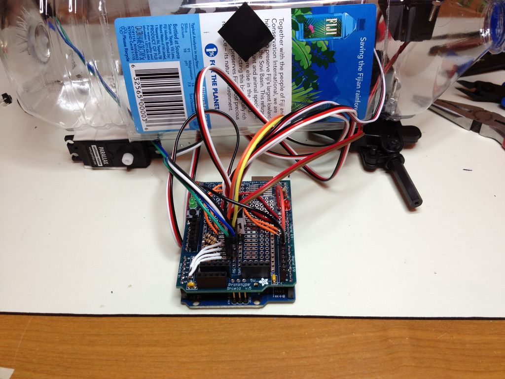
Considering working in the tight space of the Fiji Water bottle, I decided I wanted to be able to easily connect and disconnect everything (sensors, servos, etc.) from the Arduino board. So I purchased a Proto Shield, male breakaway pins, and 6″ female/female jumper wires from Adafruit. I soldered the pins to the proto shield and hooked up everything with jumpers!
The middle section of the proto board has two parallel rails connected to +5V and GND. To the right and left of these rails are 3-terminal perpendicular pads. I took advantage of this arrangement by mounting 5 (3-terminal) breakaway pins across the two rails and into the perpendicular pads. This basically gave me power, ground, and signal pins for each servo and the Ping sensor. Then, I added 4 (2-terminal) breakaway pins to the +5V and signal pads for the plug-in photoresistors.
NOTE: Notice in the photo that I did not solder the pin headers (that came with the proto kit) to the analog pins or the second bank of digital pins. I left these out so I could solder wires directly to the pads.
I connected wires to the digital PWM pins (for the servos) and to the analog pins (for the photoresistors). I also added a 10K resistor to ground for each photoresistor.
I connected wires from pins 7 & 9 of the proto board to the positive terminals of the green and red LEDs respectively.
In order to run the four servos and the Arduino, I used two separate power supplies. The Arduio runs on a 9v battery connected to Vin. The four servos and the Ping sensor run on a 4-AA battery pack, which is wired in parallel to a 6v solar panel for in-circuit charging. Since the solar panel and battery pack are closely matched, I just wired a diode between them to prevent back current.
I ran both power supplies through a DPST switch so I can power him off completely, but still leave the solar panel connected to the 4-AA battery pack. This way he can charge his batteries even when not in use.
Step 3: The Sensors
The jumper wires Adafruit sells come in a single bus of 40 wires. All you have to do is “rip off” the number of wires you need and you have a nice little pluggable cable!
Since the photoresistors would be mounted to the chassis via LED holders, I needed a quick and easy way to disconnect them from the circuit board during and after construction. So I just connected one end of the female/female jumper wires to each photoresistor lead and the other end to the pins on the proto board. The rubber spacers in the LED holders keep the leads from touching each other and shorting out.
Step 4: The Chassis
I found a cheap RC car with big cushy wheels and I thought they would work well for Fijibot. So I removed all of the “extra” parts and basically kept the rear wheels and the front end (including wheels and suspension).
I decided to use the rear wheels for power and the front wheels and suspension for steering. I attached two continuous servos to the back of the water bottle using double-sided tape. I also used double-sided tape to secure the servos to each other. Then I cut a small slot in the plastic bottle to feed in the servo cables.
For more detail: Build A Fijibot A Self-Charging Photovore Using Arduino