Topics:
1.Overview
As mentioned earlier, Arduino consists of two major parts: the hardware (the Arduino board) and the Software (the IDE). The advantage of using the Arduino is that we can build a circuit and then modify how it responds by changing the code (instead of changing the hardware). The focus of this lesson will be on building a basic circuit with an LED. We will then examine the code that makes the LED blink.
At the end of this lab, you will make the LED blink Morse Code—all through the magic of code!
2. Hardware
So you don’t have to solder things together, you will temporarily build your circuits on the breadboard provided with your kit and change the code to modify how the device responds.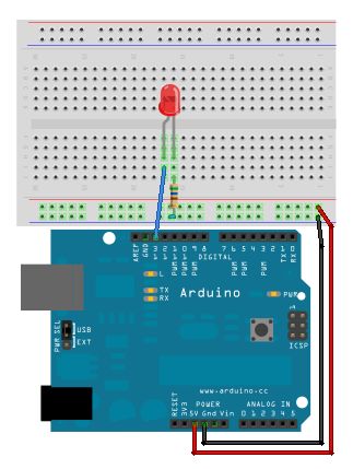 2.1 A Basic Schematic Diagram
The following is a simple LED circuit drawn as a schematic diagram. The component are circled in pale red and labelled:
If we want to use the Arduino to turn the light on and off, we can modify the above schematic diagram to the following:
This circuit calls for two pieces of hardware in addition to the Arduino, a red LED and a 1000Ω resistor. LEDs are the lights in your kit, and a red one should be easy to find, so take one out now. The resistor might be a bit trickier because resistors are labeled with stripes instead of numbers. So let’s learn a bit about resistors so we know why they are used, and can pick the right one for the diagram.
2.2 Resistors
Resistors are one of the most common electronic components so let’s explore how they work.
Unlike the LED and some other electronics components, resistors can be connected in any direction – they don’t have positive and negative leads.
Resistors reduce the flow of electricity, or current, in a circuit. All electrical components resist to some degree, even wires, but resistors are designed specifically for that purpose.
When you complete a circuit that has no resistance, current will flow through it as fast as the power source can provide it. If you have a source with a lot of available power this results in heat which may burn you or melt and ruin electrical components. A common metaphor for electrical current is water in pipes. If you have a pipe that is open to air, this is a bit like a circuit that is connected to ground. If you have a high pressure source and a wide pipe then a lot of water will flow through the pipe to air. If there is a narrow spot in the pipe somewhere this will slow the water and less water will flow out of the pipe where it opens to air. Sometimes you want a lot of water to flow to air, as in a fire hose. Sometimes you want a little water to flow to air, as in a water fountain. The same goes for electricity. Sometimes you want a lot of current because you are driving a motor. Other times you want only a little because you are driving a small LED.
Ohm’s law expresses the relation between voltage, current and resistance:
V = IR
where:
- I is current in Amps
- R is resistance in Ohms
- V is voltage Volts.
If your Arduino is plugged into a USB port two of these values are known – you usually use the 5V power pin, and USB can supply a maximum of 500mA or 0.5 Amps. Using Ohm’s law I can calculate that an Arduino circuit between the +5V pin and any of the ground pins must have a minimum total resistance of 10 Ohms and be the only thing drawing current to be safe. If your Arduino draws more than 500mA of current through USB, it will shut down to protect your computer. The computer itself may also shut down the USB port to protect itself. If this happens, try pressing the reset button on the Arduino. If that doesn’t work you may have to unplug the USB cable from the computer. Never try connecting +5V directly to ground when using the DC power plug.
Resistors are used to:
- prevent batteries from draining really quickly
- protect components
- LEDs burn out quickly if they are attached to too high a current
- some components may get really hot and melt or smoke under high current
- as a safety mechanism your Arduino will stop working if it draws too much current
- adjust the voltage at a particular point in a circuit
The last point is kind of complicated, but lots of interesting circuits make use of this voltage adjustment property. In the LED circuit, the resistor is protecting the LED.
Reading Resistor Values
Resistance to current is measured in ohms. Ohms are represented with the greek symbol Omega (Ω). You saw this symbol in the circuit schematic above. When a circuit diagram calls for a resistor with a certain resistance it is important to get the right one.
Resistors come in a very wide range of values. They are also typically very small. So rather than trying to print a resistor’s value directly on its case, a color coding system is used. This same color system is sometimes used for capacitors too, so it’s a good idea to learn it. The system goes like this:
The first three bands express ohms in scientific notation. The number represented by the first two bands is multiplied by 10 to the power of the number on the third band. Another way of thinking of this is the number represented by the third band represents how many zeros follow the numbers represented by the first two bands.
The last band represents the margin of error in the resistance value.
So, what is the smallest possible resistance value in this system? (hover over the line below to reveal the answer)
What is the largest? (hover over the line below to reveal the answer)
Here are a few examples of resistors I have laying around. See if you can correctly identify them from their colors. Hover over the lines below each resistor to reveal the answer.
You need the 1000 Ohm resistor for the LED circuit. Find the correct one in your kit.
2.3 Putting it Together
Now that we have our components picked out, let’s take another look at how they are supposed to be connected:
Notice that the schematic shows the circuit starting at pin 13 which can be controlled to turn the LED on and off. GND represents ground and is not actually in that place on the board (but it makes a nice diagram). More realistically, your board will look like this: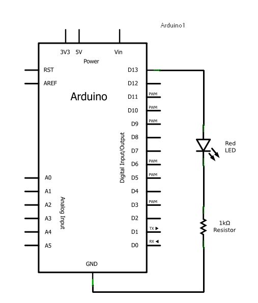 You can put the resistor on the other side of the light and you will still get the same results.
Or, you can save one wire by turning the resistor 90° to get a layout that looks like this:
Now, it’s your turn to build this circuit. Try one or all of them.
Something to watch for:
- The long lead of the LED connects to positive. In this circuit that is pin 13. If you trimmed your LED leads to the same length by mistake, you can find the negative one by feeling the raised ridge on the bottom of the led – it is flat on the negative side. This is an industry standard.
2.4 Trying it out!
Under the File menu, choose: Examples | Basics | Blink.
This is the code from last week:
Let us try running the code:
- Press the Verify button.
- Make sure your Arduino is connected to the computer.
- Press the Upload button.
- Your light should now start blinking. If it doesn’t, try reversing the light. Remember that the longer lead of an LED connects to positive.
2.5 More on Resistors and LEDs
The LED part of your circuit might look like this:
The resistor is used to prevent damage to the LED. It reduces the current coming from the output pin to a level that is safe for the LED. Technically, it is not needed in this circuit because pin 13 has a resistor built in. However, If you use an LED with any other output pin you should use a resistor.
Adjust your wires so the resistor is no longer in the circuit .
For more detail: Blinkenlights