Bingo!
My granddaughter enjoys playing Bingo, so I went out and bought her a
cheap set at a local discount store. The cards and the markers are fine,
but the spinner disk for selecting the numbers is a piece of garbage.
It flew apart about ten minutes into the first game.
True, I could have gotten a more expensive Bingo game, say for $10 or
so, one that uses a clever little hand-cranked cage and teensy wooden
decaled balls to select the numbers. But, hey, all of us Instructables
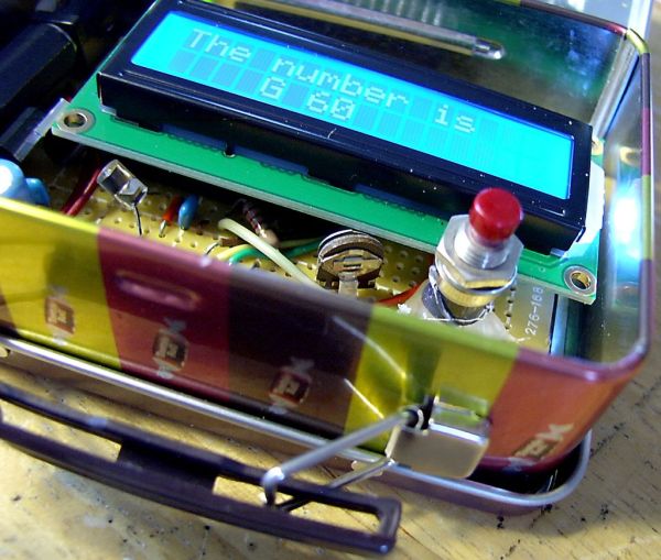
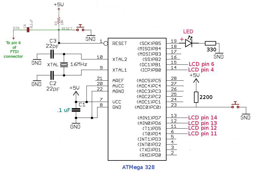
people are DIY-ers, so I decided to build a number generator using an
ATMega 328 CPU and a garden-variety 16×2 LCD display. I would test and
debug the code on my Arduino Duemillanove with LCD shield, and then build
the handy-dandy Bingo Number Generator as a stand-alone project on a
prototyping board. This means that you need not build the hardware for
this project — you can run the code on an Arduino with LCD shield and
get the same functionality. But, why tie up your development board every
time you want to play Bingo? And why cheat yourself of the fun of
making something?
***
Essentially, we’ll be constructing a stand-alone Arduino, with a built-in
LCD socket and hard-wired momentary-contact switch. It will lack only
the female header strips for plugging in shields, though you could
optionally add those, too. Consider this project as a sort of prototype
all-purpose microcontroller board with display. So, even if you’re not
a Bingo enthusiast, this should still be of interest.
Step 1: What You’ll Need
This project does require a fair amount of hardware,
but none of the components listed below are difficult
to find or particularly expensive.
ATMega 328 CPU 6.00
(with bootloader)
16×2 LCD display 4.00
Protoboard 3.49
[Radio Shack 276-168, or similar]
LM7805 5v regulator .50
1N4001 diode .25
resettable polyfuse .35 [optional, but recommended]
[All Electronics, catalog # RXE-065, or equivalent]
40-pin male header strip .75
40-pin female header strip .75
28-pin IC socket, narrow .75
mini pushbutton switch .50
momentary contact switch .50 [generic]
16-MHz crystal 1.00
mini 10K trimpot .25
330-ohm resistor, 1/4 watt (2x) .50 [anything from 220 to 1k is okay]
LEDs (2x) .35 [generic, one red, one green]
power jack, coaxial [2.1 mm] .75 *
power plug, coaxial, [2.1 mm] .75 *
[Radio Shack 274-1569, Size M, or similar]
100 uF capacitors, 25-35v (2x) 1.00 [Don’t get the 16v kind.] **
10 uF capacitor [optional] .50 [for extra filtering]
22 pF capacitors (2x) .50
.1 uF capacitors (2x) .50
solder
* Make sure you get a matching set of plug and jack.
There are several similar-looking ones in approximately
the same size, and they are NOT necessarily cross-compatible.
[I could go on a rant about lack of standardization in plugs and jacks,
but this is not the appropriate time or place.]
** If you use a filter cap with at least a 25-volt rating, then you can
plug in a 12-volt power supply with no worries. A 16-volt filter cap
may not give you enough tolerance.
Hopefully, you have at least a few of these components in your spare
parts box. If you had to buy each and every one of them, the total could
easily run over $20.
Step 2: The Power Supply
Refer to the power supply schematic (first figure) for this step.
Let us build the board power supply as a separate module on one corner
of the protoboard.
To begin with, we mount the 2.1 mm coaxial jack on a far corner of
the blank protoboard. The bottom two prongs on the jack pass through holes
in the protoboard (we will connect the ground prong later). To affix the
jack to the board, I used hot-melt glue, applied with a glue gun. This
is quick and convenient, and it creates a bond more than strong enough
to withstand repeated insertion and removal of the power plug.
[See illustrations.]
Now solder a polyfuse to the rear terminal (positive) of the coaxial jack.
The function of the polyfuse is to protect the circuit against overloads,
such as those caused by shorts or plugging in a wrong-polarity power plug.
If there is an overload, the polyfuse functions as a circuit breaker.
The polyfuse connects, in linear fashion (see illustration) to the diode.
The function of the diode is to block current from a reversed-polarity plug.
Finally, the wire leading from the banded end of the diode (negative)
goes to the input of the LM7805 regulator IC.
Let’s position and connect up the remaining components of the power
supply section. There are three capacitors, an indicator LED, and a
current-limiting resistor for the LED. Refer to the schematic and the
pictures.
Note that we’re using a 4-pin male header strip, with jumper, as an on-off
power switch. This is cheaper and simpler than mounting a toggle switch.
The +5 volt input connects to the left pin of the on-off header,
and the second pin of the header has a wire connected as the output.
Therefore, when these two pins are bridged with a jumper, then the
main circuit gets power. Removing the jumper
(or moving it to pins 3 and 4 of the header) cuts the power.
Be careful to observe polarity. The center pin of the power jack is positive.
Choose an external plug-in power supply with an output plug
that likewise has a positive center. But, you need not worry too much
about this. If the polarity is wrong, the 1N4001 diode will block current
flow. And if there is a short, then the polyfuse will open. In either case,
no damage should result. But, our neither will our project work.
Time to test the power supply. Plug in a 9-12 volt DC source.
Does the power LED light up? Yes, it does. If you have a multitester,
check whether we’re getting a 5-volt output at the positive pin of the
100 uF capacitor. Okay so far?
(with bootloader)
16×2 LCD display 4.00
Protoboard 3.49
[Radio Shack 276-168, or similar] LM7805 5v regulator .50
1N4001 diode .25
resettable polyfuse .35 [optional, but recommended] [All Electronics, catalog # RXE-065, or equivalent] 40-pin male header strip .75
40-pin female header strip .75
28-pin IC socket, narrow .75
mini pushbutton switch .50
momentary contact switch .50 [generic] 16-MHz crystal 1.00
mini 10K trimpot .25
330-ohm resistor, 1/4 watt (2x) .50 [anything from 220 to 1k is okay] LEDs (2x) .35 [generic, one red, one green] power jack, coaxial [2.1 mm] .75 *
power plug, coaxial, [2.1 mm] .75 *
[Radio Shack 274-1569, Size M, or similar] 100 uF capacitors, 25-35v (2x) 1.00 [Don’t get the 16v kind.] **
10 uF capacitor [optional] .50 [for extra filtering] 22 pF capacitors (2x) .50
.1 uF capacitors (2x) .50
solder
For more detail: Binguino: An Arduino-based Bingo Number Generator