
Summary of Bike taillight with a twist using Arduino
Summary: A DIY RGB bicycle taillight using 2x AA cells, a boost converter to 5V, RGB SMD LEDs, an AVR microcontroller (ATmega168 TQFP32), and custom PCBs. The design multiplexes LEDs via 3 GPIO-driven anode groups and 8 cathode GPIOs, allowing PWM color mixing or full-brightness mode. KiCad was used for schematics and Gerbers; BatchPCB fabricated the boards. Current-limiting resistors (calculated with Ohm's Law) protect microcontroller pins and LEDs; measured forward voltages and small potentiometers were used to balance white.
Parts used in the RGB bike taillight:
- 2x AA cells (battery pack)
- Boost converter (to 5V)
- RGB SMD LEDs (PLCC6 5050)
- Microcontroller ATmega168-20AU (TQFP32)
- Current limiting resistors (0805 SMD)
- Resistors/potentiometers (for balancing white)
- Capacitors (0805 SMD and 1206 SMD)
- Custom printed circuit boards (BatchPCB)
- Headers: ICSP and 6-pin serial header
- Perfboard and general soldering gear
Let’s face it. Taillights are boring.
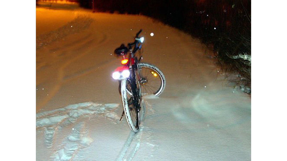
At best they go ‘blink blink – look at me! I’m blinking – woohoo’ all the time. And they’re always red. Very creative. We can do better than that, maybe not much, but still better than just ‘blink blink’. I was riding my bike during new year celebrations and people liked it, and not all of them were drunk 😉
The rest is pretty straight forward: 2x AA cells, boost converter for 5V, some RGB LEDs, the obligatory micro controller, custom printed circuit boards from BatchPCB, perfboard and the usual soldering gear.
Step 1: Main schematic
In the schematic you’ll just find the cpu, the LEDs, a few resistors and capacitors. That’s all. There’s a few headers too. The boards have an ICSP header for flashing a bootloader and a 6pin header for convenient serial upload. The last 2 headers are mirrored and contain power, I2C and two more GPIO/ADC pins.
3 GPIO pins with 3 current limiting resistors are used to supply current to all 8 anodes of a single color. Individual LEDs are turned on or off using 8 GPIO pins to drive the cathodes. Depending on the type of operation the LEDs are either multiplexed (PWM for more colors) or fully on (higher brightness).
Some info on the packages I used for this board:
– ATmega168-20AU: TQFP32 SMD
– LED: PLCC6 5050 SMD
– Resistors: 0805 SMD
– Capacitors: 0805 SMD, 1206 SMD
 rgb_led_toy-schematic.pdf(766×539) 62 KB
Step 2: Dealing with the LEDs
I won’t go into great detail here, as this has been covered elsewhere numerous times. You just have to make sure you don’t exceed the micro controller’s maximum output current per pin (about 35mA or so for AVRs). The same is true for the LEDs current. As you can guess from the picture, I used one of the SMD LEDs to figure out the resistor ratio to get well balanced white light. There are three 2k something potentiometers on the other side. That’s all. In this case I ended up with resistors ranging from 90 to 110Ω, but that depends on the kind of LED you get. Just use a standard multimeter to determine the LED’s forward voltages V_led and you’re in business.
Using Ohm’s Law, you can calculate the values for current limiting resistors for small LEDs like so:
R = ( V_bat – V_led ) / I_led
I_led should not exceed any current limit of the parts you use. Also this approach is only good for low current applications (maybe up to 100mA) and should not be used for Luxeon or CREE LEDs! The current through LEDs is temperature dependent and a constant current driver should be used.
For more detail: Bike taillight with a twist using Arduino
- What microcontroller is used in the project?
An ATmega168-20AU in TQFP32 package is used. - How are the RGB LEDs driven?
Three GPIO pins drive anode groups and eight GPIO pins switch cathodes, enabling multiplexing or full-on modes. - Which design tool was used for schematics and PCB?
KiCad was used for the schematic and PCB design. - Where were the PCBs fabricated?
Gerber files from KiCad were used with BatchPCB to fabricate the boards. - How are current limiting resistor values determined?
Resistor values are calculated with Ohm's Law R = (V_bat - V_led) / I_led using measured LED forward voltages. - What SMD packages are used for LEDs, resistors, and capacitors?
LEDs are PLCC6 5050; resistors 0805 SMD; capacitors 0805 and 1206 SMD. - Can the LEDs be PWM multiplexed for more colors?
Yes, multiplexing with PWM is used for more color mixing. - Are there headers for programming and serial upload?
Yes, there is an ICSP header for bootloader flashing and a 6-pin header for serial upload.
