Magnetoception is the ability of some animals to detect magnetic fields as a means of orienting themselves. Although humans do not seem to posses the same biological mechanisms that allow other animals to sense magnetic fields, there are still many ways that we can improve our sense of spatial orientation.
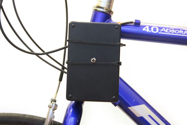
This project is an attachment to your bicycle that beeps to let you know that you are moving in the direction of magnetic north. It uses a parallax digital compass module, an Arduino, and a piezo buzzer to give you directional feedback as you bike. The basic idea here is that by providing a constant source of stimuli in a certain direction, you might find yourself becoming more aware of other visual or sensory cues in your commute that indicate your orientation: geographical landmarks, air currents, inclines, or the position of the sun, moon, and stars.
(1x) Parallax 3-Axis Compass Module Radioshack 276-123
(1x) 85dB Piezo Buzzer Radioshack 273-060
(1x) Arduino Uno REV 3 Radioshack 276-128
(1x) 9V Alkaline Battery Radioshack #23-866
(1x) Heavy-Duty 9V Snap Connectors Radioshack #270-324
(1x) PC Board with Copper Radioshack #276-147
(1x) SPST PC-Mountable Submini Toggle Switch Radioshack #275-645
(2x) Male Header Pins Jameco 103393
(1x) Female Pin Sockets Jameco 308567
(1x) 9-Volt Battery Holder Radioshack 270-326
Additional Materials:
Heat Shrink Radioshack #278-1611
22 Gauge Wire Radioshack #278-1224
Solder Radioshack #64-013
zip ties
Drill
Screwdriver
4-40 x 1″ nuts and bolts
Step 1: Schematic
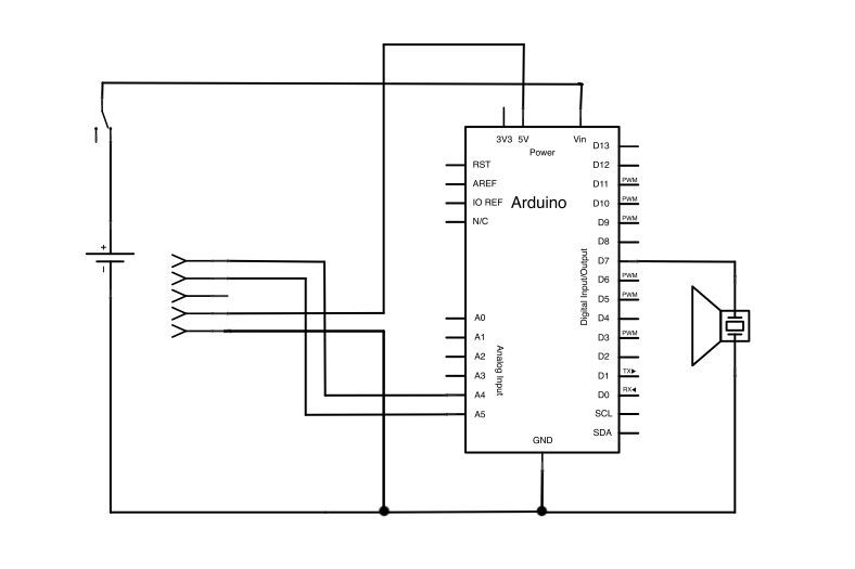
The schematic above shows how simple this project is. A 9V battery and switch are connected in series to the Vin and ground pins of the Arduino- this is the power supply for the project. The Arduino supplies power to two pins of the compass module (see note in the image above) and analog pins A4 and A5 are used to receive data from the compass module. the piezo buzzer is controlled by Arduino digital pin 7.
Step 2: Solder header pins to perf board
Solder three rows of header pins to the copper side of the perf board so that the Arduino snaps on. The headers pins should fit inside the Arduino’s power pins, analog inputs, and digital i/o 0-7. I did not solder header pins for pins 8-13 because the spacing between digital pins 7 and 8 is not the standard 2.54mm spacing. It is a little challenging to solder the header pins to the copper side of the board (I got some extra solder on some of the copper pads), but it is necessary so that the compass module can snap on the perf board without touching the Arduino.
Step 3: Parallax compass
Solder a row of 5 female sockets on the protoboard as shown in the images above. The Parallax compass chip should fit nicely in this socket. Connect the pin labelled ground to Arduino’s ground, Vin to Arduino’s 5V, SCL to Analog 5, and SDA to Analog 4 as indicated in the schematic above.
Upload the following code onto the Arduino. It will print the raw x, y, and z data from the compass chip (the directions are indicated on the chip in figure 4). If you have wired everything correctly you should see the raw data printed on your serial monitor (control/command+shift+m) in the Arduino IDE. I found this code on the parallax website.
Step 4: Piezo buzzer
The piezo buzzer says that it should run off a 9-16V supply, but if you hook it up to 5V it will still run, just somewhat quieter. I didn’t necessarily want it to buzz at maximum loudness so it worked out well to hook it directly to one of the Arduino’s digital pins for this project. If you really want to run the buzzer at 9V, you can wire it up with a transistor to the battery supply and use a transistor to switch it on and off.
Solder the red lead from the piezo buzzer to digital pin 7. Solder the black wire to Arduino ground.
(1x) 85dB Piezo Buzzer Radioshack 273-060
(1x) Arduino Uno REV 3 Radioshack 276-128
(1x) 9V Alkaline Battery Radioshack #23-866
(1x) Heavy-Duty 9V Snap Connectors Radioshack #270-324
(1x) PC Board with Copper Radioshack #276-147
(1x) SPST PC-Mountable Submini Toggle Switch Radioshack #275-645
(2x) Male Header Pins Jameco 103393
(1x) Female Pin Sockets Jameco 308567
(1x) 9-Volt Battery Holder Radioshack 270-326
For more detail: Bicycle North Indicator using Arduino


