Most electronics projects require some common stuff like regulated power supply, input tact switches, and output LEDs during prototyping and testing phase. Wiring these things on a breadboard for every new project could be time consuming and boring. We introduce you the Basic Experimenter Board, a general purpose development tool that will not only reduce the prototyping time for your next project but also free up plenty of space on the breadboard. It features regulated 3.3V and 5.0V power supply on board along with four output LEDs, four input tact switches, one output buzzer with driver circuit, a potentiometer for simulating analog input, and a 480-point breadboard for rapidly prototyping and testing your electronic circuits.
Features:
- Regulated 5.0V and 3.3V power supply. Maximum DC input is 15V, and maximum output current is 500mA. The board contains a 500mA PTC fuse for overload or short circuit protection.
- Four LEDs for digital outputs. The current limiting resistances are already implemented on board. All LED access pins (available on JP1 header) are active HIGH (which means a logic high applied to the LED access pin turns it on).
- Four tact switches for digital inputs. The output logic high voltage of the tact switches can be set to 3.3V or 5.0V through a 2-pin shunt jumper on JP4 header. The tact switches outputs (available on JP1 header) are high during normal condition and are low when pressed.
- On-board buzzer with a transistor driver circuit. The buzzer is continuous-type and activates when a logic high is applied to the BUZ input pin on JP1.
- Potentiometer for simulating an analog signal. The range of the potentiometer output can be set to 0-3.3V or 0-5.0V through a 2-pin shunt jumper on JP6 header. The potentiometer output is accessible through the POT pin on JP1.
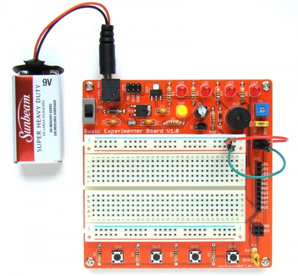
You can buy Basic Experimenter Board from our Tindie Store. The package consists of a fully assembled Basic Experimenter Board, a 9V battery clip, and a set of male-to-male jumper cables with varying length (see the picture below).
For More Details: Basic Experimenter Board for easy prototyping of electronic circuits