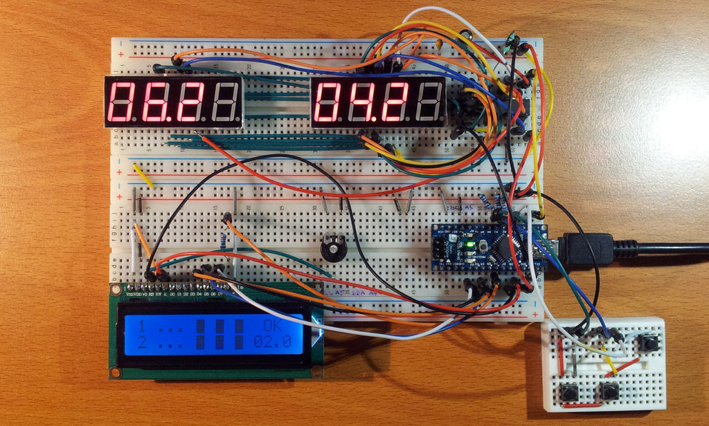
Upon the needs of the (2014) World Barista Championship Rules and Regulations, an adequate and precise time measuring is needed during the competition. These measurements are usually done by regular stopwatches with all the benefits (ease of use, common availability) and drawbacks (two stopwatches needed for each judge, as well as some mathematics are necessary for supervision).
This Arduino-based stopwatch originally designed to meet all the requirements of this situation, finally to make judges’ work seriously simpler, yet at least as acceptalbe as the good old way. My goal were to meet the requirements of Rules and Reglations 2.2.1.H (verbosely defined under 13.3.7.). In short: during the competiton, the extraction times within each beverage category should be within 3 second variance. For example, if the competitor extracts a set of espresso drinks (four servings in two two-servings brewing), de difference between each brewing time should be less than 3 second. If first brewing is 29.1 second, second brewing should be between 26.1 and 32.1 second (excluding both 26.1 and 32.1), otherwise the competitor will get a penalty.
Benefits:
- one watch instead of two,
- designed and built to meet WBC/WCE requirements to help judges,
- can be upgraded, changed due to the changes of Rules and Regulations and/or different type of competitions,
- make all the measurements and analysis,
- it’s hard to be hacked by the judge to make unwanted and unfair handicaps to certain competitors (see 15.0 in Rules and Regulations),
- easy to use,
- planned to be upgradable to on-line/off-line logging and other features,
Drawbacks:
- not official,
- still a prototype.
Step 1: Main component descriptions
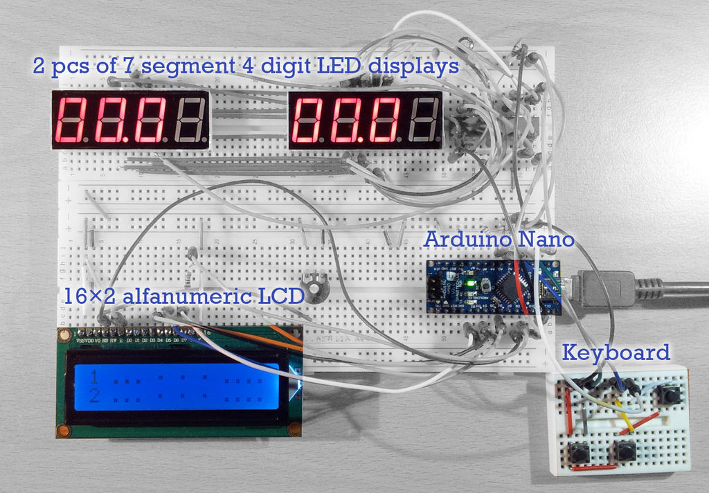
This stopwatch has four main components:
- two independent 3 + 1 digit 7 segment displays,
- one keyboard with three keys to control,
- a 16×2 digit alphanumeric display,
- an Arduino board (now a Nano 328 v3, some other models are also accepted and may be working properly).
1. Main displays
Both have a very simple goal: to show measured time. To avoid unfair/dishonest behaviour of judges, actual (counted) time is not displayed, instead a mark shows that the measurement is running. So the judge has no any information about the elapsed time, so unable to stop the measurement within the 3 second barrier, whatever the competitor stopped the brewing or not. After the end of the first measurement, the measured time will shown on the display in 1/10 second precision, and this time will remain on the display until the next measurement has finished (on the same stopwatch). Most of the competitions are used to have a two grouphead espresso machine, where the competitors should use two groupheads to produce a set of drinks. Brewing time on each head should be measured independently, so two independent stopwatch and display needed.
2. Keyboard
This simple keyboard have two goals: to measure time (start/stop and reset the stopwatches) and control the menu of the stopwatch.
Each stopwatch has its own start/stop button. After initialization/reset, the first push of the start/stop button will start the measurement, second push will stop. After all six measurements (two measurements of three groups), the push of the third button will reset the values.
3. 16×2 digit alphanumeric display
There are a lot of information are on the display, as well as some future features will use it. Detailed information about the display will discussed later.
4. Arduino board
With some changes, almost any Arduino-compatilbe board can be used, except Esplora, Due and Leonardo. Some future software development may cause the exceeding of available memory, so “the bigger is better” rule may be true here.
Other components will be listed on the next page.
Step 2: Component list
- Arduino compatible board (except Leonardo [no SPI], Due [3.3 V], Esplora/Robot/Lillypads [all designed for different purposes], I suggest to use AtMega328 based boards like Nano rev 3.0 or Mini which has full SPI compatibility.
- 2+1 pcs breadboards (2 pcs 820 hole, and one 170 hole mini breadboard)
- tons of jumper wires, both rigid (34 pcs) and flexible (30 pcs),
- 2 pcs 4 digit 7 segment LED displays or 8 pcs 1 digit 7 segment LED displays (common cathode type)
- 1 pc Maxim MAX7221 or MAX 7219 LED display driver (shift register)
- 1 pc 16×2 digit LCD display (Hitachi 44780 driven)
- 1 pc 10k potentiometer (linear)
- 3 pcs microswitches (pushbuttons)
- 1 pc 0,1 mF 6.3V tantalum capacitor
- 1 pc 10 mF 6.3V electrolytic capacitor
- 1 pc 220 ohm resistor
- 3 pcs 10k resistors
- 1 pc 33k resistor
Alternative LCD connection:
- 1 pc BC337 NPN transistor
- 1 pc 270 ohm resistor
- 1 pc1k resistor
Due to wide availability of components and geographical differences between prices, it’s almost impossible to guess the cost of this project. Mine is around or even under 30 USD with a lot of components found in cheap starter kits from SainSmart. Of course, original Arduino boards and higher quality displays may get the price higher, up to – a guess – 70 to 80 USD.
Step 3: Schematics, wiring
Please see Fritzing file.
Note that almost all Arduino boards has a somewhat different pinouts for SPI connection (which is used by max72xx), as well as digital I/O and analogue input pinout. If you have any question or comment, please, feel free to write me.
In general, you’ll find some tips on pin numbering in Fritzing file (just go over a pin of an IC to show pin number).
Important notices
MAX7221 to Arduino
First of all, Maxim MAX7219 and MAX7221 has a different pinout. I’ve used 7221 for this project, but 7219 is still good. There is only a slight difference between these two shift registers which literally not affect the usage of the stopwatch. For wiring MAX72xx to Arduino, you have to use only three wires: SPI “MOSI”, “SCK” and “SS”. For Arduino Nano 328 and MAX 7221 the wiring should be:
- Arduino Pin 10 to MAX7221 Pin 12 (SS / LOAD)
- Arduino Pin 11 to MAX7221 Pin 1 (MOSI / DataIn)
- Arduino Pin 13 to MAX7221 Pin 13 (SCK / CLK)
MAX7221 to LED displays
It is very important to use common cathode type displays. It’s not mandatory to use 4 digit 7 segment displays (like 5641AS I’ve used). If you have common anode type display, a much complicated (yet seriously costy) wiring is needed, so I don’t recommend it.
Each display has at least 9 pins for each digit (common cathode pin is often doubled on 1 digit 7 segment displays). Each has a unique identifier from A to G, and one for decimal point (ofter marked as DP). As we use a shift register, the ‘A’ pins of each display should be connected to each other, as well as to pin ‘A’ of MAX7221 (it’s pin 14).
If you use single digit displays, a lot (literally 8×8 = 64) individual wire should be used, which is not the most space and money consuming solution. That’s why I recommend to use 4 digit 7 segment displays (which requires only 2×8 = 16 wires for anodes). As a reference, here is the pinout for MAX7221.
- A –> 14
- B –> 16
- C –> 20
- D –> 23
- E –> 21
- F –> 15
- G –> 17
- DP –> 22
Finally, you should connect each cathode of each digit to the specified pin of MAX7221. At this point, first digit marked DIG0 on 7221. Here is the pinout for each digit (please note that all pinout diagrams starts with DIG0, which is the first digit):
- 1. –> 2
- 2. –> 11
- 3. –> 6
- 4. –> 7
- 5. –> 3
- 6. –> 10
- 7. –> 5
- 8. –> 8
Each LED cathode pin should be directly connected to MAX7221, and never should be connected to each other.
MAX7221 power and other connectors
Due to high frequency characteristics of almost every shift registers, it’s recommended to put at least one capacitor to the power input of MAX7221. I’ve used a 10 mF and a 0.1 mF capacitor for this purpose and didn’t experienced any error in work. If you have, try other values. All capacitors should be as close to the input as possible.
It is possible the change the brightness of the LED displays within the arduino library of MAX72xx (LedControl.h), but it is necessary to properly drive each segment with a desired forward current. For further reference, please see MAX7221 datasheet here. For my displays, a <20 mA forward current and 1.5 forward voltage could be set with a 33k resistor connected to pin 18 of MAX7221 (R6 in Fritzing file). As almost anytime, some attention needed to protect your Arduino board and your MAX 7221 too. I do not recommend using any forward current over 20 mA.
LCD to Arduino
It’s a very common connection. As I mentioned in Fritzing file note, this wiring should be changed due to different Arduino boards. At this case, you should change the LCD setup line in the Pre-Setup part of the sketch. This setting/wiring can be used for Nano328 compatible boards and common Hitachi 44780 driven 16×2 character alphanumeric displays.
It’s your decision to use a BC337 or similar NPN trasistor to drive LCD backlight. I’ve experienced that almost every common LCD can work properly with a simple direct drive through a 220 ohm resistor far under the 20 mA current limit of Arduino pin. For backlight setting, it’s necessary to use a PWM pin for this purpose (see diagram in Fritzing file).
It’s rather common to get a blank LCD at first startup due to improper setting of contrast potentiometer (10k, marked as R1 in Fritzing). I suggest to rotate and try to find the best setting before change the wiring. Negative (white on black, white on blue – that I’ve used) type LCD displays are harder to setup and harder to read than positive types. By the way, usually seriously cheaper.
For more detail: Barista championship brewing stopwatch • Introduction using arduino


