In short: I developed a portable, battery powered device that sounds an alarm when your bag or purse is moved. Once armed, can only be turned off by your secret code.
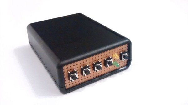
The device is built off an Arduino compatible Trinket Pro, using an off-the-shelf project box with PCB.
– ———————————————————————
Problem I had:
When I go to a happy-hour or a cocktail party, I often have my computer bag with me. But I do not want to carry it around with me, so I put it down somewhere, hoping that no one takes it. I may check on it periodically, or stand so that my bag is in my view, but I am still concerned someone may take it. Or I may be traveling, taking a nap at an airport or when waiting for train and be concerned that it might disappear while I am sleeping. Or any number of circumstances in my life where I need to protect my bag from being stolen.
Solution I built:
I built a small, portable alarm to warn when my bag has been moved. It is 9V battery operated, but without an on/off switch, otherwise the potential thief could just hit the off button. As a result, I have an ‘arm’ button, and then you have 20 seconds to but the bag/purse + device stationary. After being armed, if the bag/device is moved for more than 5 seconds and above a threshold level, it sounds an alarm until the correct code is entered. The secret code uses a 4 button interface, but the code can be any length.
Genesis / special motivation:
My parents were recently traveling abroad, and their bag (with their camera) was stolen while they slept. I decided to build this for them for a Christmas present, so that they would not have to go through that again. I was thus forced to build this over the course of December, which was great motivation.
———————————————————————-
If you want more info on how I made this:
I also blogged about making this (and the challenges I faced along the way) on my personal blog at MakerSelf.com.
———————————————————————-
Improvements are coming! Improvements are coming!
I have been blown away by the interest in this project. Thanks to all the helpful comments I have received here and other inputs I have received, I intend on making an improved version of this project. Right now, I am thinking about adding a rechargeable battery and RF/Bluetooth. If you would like to be updated when that project is done feel free to sign up for updates (I can’t embed a form here, so that is a direct link to a form to sign up to get updates). I don’t intend on sending out very many updates: I am fairly lazy and hate email!
Putting this up publicly and having a signup is in part to give me motivation to complete the improvements: if there is a lot of interest, I will find the time!
Step 1: Gather your components
Obtain or purchase the following components:
Core components:
- A Trinket Pro as the brains of the show. You can get one from Adafruit or Hackaday.
- An accelerometer to tell when the device is moving. You can use a variety, but I used the GY-521 available from Amazon or Deal Extreme (or many other sources). The GY-521 is a bit overkill, as it also includes a gyro that I did not use in the product, but it was relatively affordable compared to commonly available accelerometers.
- A speaker/peizo to act as an alarm. You can use various depending on your preference for sound, but I used this one from RadioShack. I chose it based on the loud sound but low current consumption, and that it takes a broad range of voltages (3V-28V) so I wouldn’t need to be too fussy about battery voltage.
- Four buttons to input a code
- One button to turn the device on, paired with a power circuit that allows the device to be turned on by hardware (the button), but off by software (by putting a pin to low)
- Two LEDs: one green LED to tell status, and one yellow LED as a low battery warning
Other components include:
- Project box. I used a project box with an integrated PCB and battery compartment, available from Amazon.
- Piece of perf board (doesn’t need to be very big, just enough to cover one end of the project box)
- 2x P-Channel MOSFET transistor. From Mouser here. These are TO-92 packages, so fairly small. The max current is below what I anticipate would ever be needed to power all the components.
- 2x N-Channel MOSFET transistor. From Mouser here.
- 2x 330 ohm resistor (for current limiting on the LEDs). This does not have to be the exact resistance value, but in the general ballpark.
- 12x 10k ohm resistor (for ground ties, battery monitor pin voltage divider, etc.). The ground ties don’t have to be exactly 10k, but just high enough, and the voltage divider just needs to be two the same value. I also tried 1k for these and it worked just fine.
- 1x 47k ohm resistor (for current limiting for the battery monitor pin). Also doesn’t need to be exact.
- 1x 100nF capacitor (for dealing with any spikes on the battery monitor pin)
- 1x 6 pin female header
- 2x 12pin male headers (for the Trinket Pro, and may come with your Trinket Pro)
- 1x 9V battery clip
- 1x 9V battery
- Hook up wire (multi color if you want to keep things straight for yourself)
- Some thin foam padding (e.g. from envelope padding). This is optional, to make the battery fit more snug.
Step 2: Gather your tools
To complete this project you will need:
- Soldering iron and solder
- Hot glue gun
- Dremel or similar saw (for cutting the perf board)
- File (for filing the cut perf board)
- Helping Hands and tweezers, for helping to hold and place the components
- Wire snips
- Wire stripper
Step 3: Plan how to lay out the components on the PCB
I had prototyped this on a breadboard, so to make this an actual project I had to think about how to lay out the PCB. The PCB I used is the board that came with the project box, which you can see in the photo of the project box and components.
I put the schematic, fritzing wiring diagram, and the diagram of the layout on the PCB in the pictures.
For the Fritzing wiring diagram: I have used orange to indicate 9V rail (stripped indicates that it is only sometimes on), and red to indicate 5V rail. Ground is consistent as black. Yellow connects to the LEDs, Cyan to the push buttons, purple is the input to the battery monitor pin, blue is the SCL and SDA for the accelerometer, and green are the two switching pins (to turn the power circuit on and the speaker on.
For the layout on the PCB: I laid all the components out on the board by drawing it out on a piece of paper (just made it easier). The end result is in the picture, and some comments to explain how it works:
- The two headers for the Trinket Pro are marked in the light blue boxes, with the USB port for the Trinket Pro pointed to the left. The headers I used on the Trinket Pro had enough space so I could run wires underneath it (you can see the gold, green, pink, red wires all underneath the board. These components and wires are actually placed on the OTHER side of the board, with the soldering on this side. For the GY-521, I actually soldered on a header, and then put the GY-521 into the header. I had enough head room (barely) in the project box to do this and it made it easier to fit the wires underneath the GY-521.
- The grey lines are passive components, and are marked as what they are (e.g. 10k is a 10k ohm resistor).
- The black, red and orange squares are ground, +5V and +9V rails. You will need to solder all connections in this square together.
- The transistors are in an arrow head pattern, allowing the drain of the N-Channel MOSFETS to go directly to the gate of the P-Channel MOSFET. The top of the arrow head is the common source (+9V) for the two P-Channel MOSFETs. With the TO-92 packages, the P and N MOSFET pairs should either face each other or have their backs to each other. The left ones should face each other (rounded part towards rounded part) and the right ones should have backs to each other (flat part towards flat part). Confirm the pin layout for your transistors.
- The five buttons and the two LEDs go on a piece of perf board that would replace the end piece of the project box was removable (see the small black rectangular piece in the project box picture above. Where those connections are (buttons and LEDs) are marked on the diagram above. Additional external connections are the battery + and – from the battery clip, and the speaker would just hang loose and be stuffed in on top of the Trinket Pro when closing up the box.
For More Detail: Bag movement alarm for theft prevention