Summary of Automatic Chicken Coop Door – Arduino Controlled.
This article details a modular, Arduino-controlled automatic chicken coop door with adjustable opening/closing times and remote override capabilities. Powered by 9V DC (battery/solar), it uses a servo motor to lift a counterweighted timber door and a solenoid to lock it. The system includes an RTC module for timekeeping and an RF module for remote control, allowing owners to automate daily routines or manually intervene as needed.
Parts used in the Automatic Chicken Coop Door:
- Arduino UNO 3
- 4 digit, 7 segment LED display
- RTC module
- RF module
- Potentiometers
- Servo motor (MR-996)
- 6V - 12V Solenoid
- Rotary encoder with push button
- Timber scraps (frame and door)
- Pivot rod (printer rod or threaded rod)
- Hinge
- Aluminium lifting arms
- Heavy bolts and nuts (counterweights)
This Instructable is for the design of an automatic chicken door with manually alterable opening and closing times. The door can be opened or closed remotely at any time.
The door is designed to be modular; the frame, door and controller can be constructed and tested in a place away from the coop and then simply bolted on the existing coop opening.
It runs off 9Vdc, so it can be powered from plugpack or a battery and solar panel to charge the battery.
It uses a solenoid to lock to the door closed and to hold the door in the open position.
Major parts include:
Arduino UNO 3.
4 digit, 7 segment LED display
RTC module
RF module
Potentiometers,
Servo motor,
6V – 12V Solenoid,
Rotary encoder with push button
The door and its frame can be made from timber scraps. The door pivots upwards around a rod (taken from a printer in my case) and is counterweighted to lessen the torque needed to raise the door.
The tools to build it include:
PC with Arduino IDE to program the Arduino,
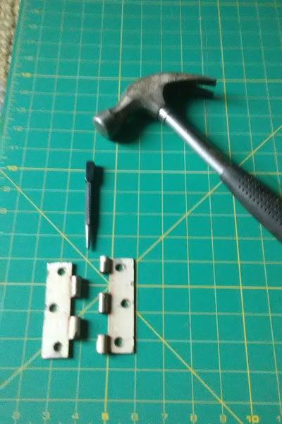
Hammer,
Saw,
Soldering iron,
Wire cutters,
Drill,
Screw driver.
I built this automatic chicken door to save me the twice daily task of opening and closing the door in the morning and evening. Chickens are great providers of eggs, manure and entertainment, but getting up early to let them out the coop – especially in Winter – was drudgery. And then making sure I was home in time to close them in really restricted my freedom to come home late.
Chickens follow a daily routine of returning to a coop around sunset and waking up around sunrise. The times they go in and out is not exact and is influenced on the weather of the day and ambient light. Should a chicken be seen to be too late to enter after the door closed, the door can be remotely opened then closed. The door can be closed during the day should the owner need to stop broody chickens from entering.
As sunrise and sunset times vary throughout the year and depend on the latitude, any door controller needs to track the time of day, the day of the year and know the latitude of the location. This requirement can be acomplised with software or a suntracker, but in this design uses manually adjustable open and close time settings to keep things simpler.
As sunrise and set times only change by a few minutes from one day to the next, the door controller settings need only be adjusted once a week.
When an owner has a sense of their chickens’ roosting routine, they can easy adjust the open and close times.
The opening time can be adjusted from 3am to 9am and the closing time from 3pm to 9pm. These times suit latitudes from 12 to 42 degrees from the equator (Darwin to Hobart in Australia) and cover the longest and shortest days of the year. .
In essence the door controller is a clock with two settable alarms with manual overide.
Step 1: Frame and Swing Door
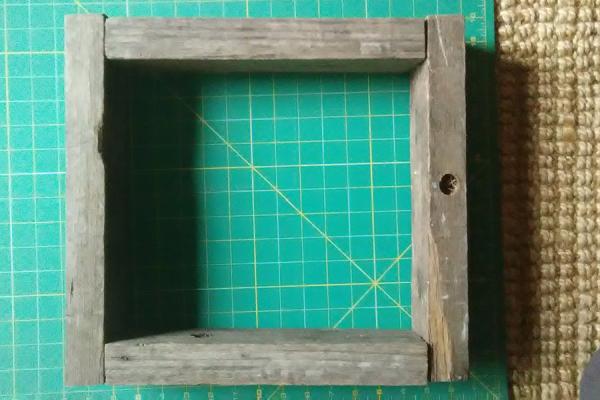
The frame is made to be secured over the existing coop opening. The door swings upwards like a garage door. This design has the advantage over automatic doors that slide upwards or sidewards for coops where the roof slopes over the existing door or the existing opening is adjacent to a wall.
1. Remove the existing door.
2. Choose a frame size that fits over the existing opening.Two dimensions of the frame are important – the height of the frame and the width of the timber. The door swings from a horizontal pivot and the length from the pivot to the frame (“D” in diagram) is the same as the width of the timber. This means that when the door is open, the section of door above the pivot does not interfere with the coop wall.
3. Choose a material for the frame that is sturdy and weather proof. I used red-gum which proved to be sturdy but heavy. Outdoor pine would be easier to work with.
4. The door itself should be light, rigid and weather proof.
Step 2: Pivot Rod and Swing Door Sizing
The swing door dimensions should be such that the width of the door fits over the inside edges of the frame. The height of the door is smaller than the inside of the frame height.
1. Find a rod about 5mm (1/4 inch) diameter and length equal to the width of the frame.I used the rod from a dismantled printer, but threaded rod would suffice. Another source of rods are from metal clothes drying racks. A rod can be cut with a bolt cutter or hacksaw. Scrape the coating off the metal with a blade.
2. Cut two grooves into the frame at a length “D” (in diagram in previous step) from the frame top opening and a depth of the diameter of the pivot rod.
3. Find a hinge whose pin diameter is the same or slightly larger than the pivot rod. Knock the pin out with a hammer and center punch. If you don’t have a center punch, use a large nail or similar pin.
By fluke, the printer rod pivot I used was a perfect fit for the first hinge that came out of my junk box.
4. The weights of the bottom section of swing door below the pivot and the top section above the pivot need to be similar to take the strain off the servo motor that opens the door. This can be achieved this with some heavy bolts and nuts that were drilled into the top section of the door.
Step 3: Servo Motor and Lifting Arms.
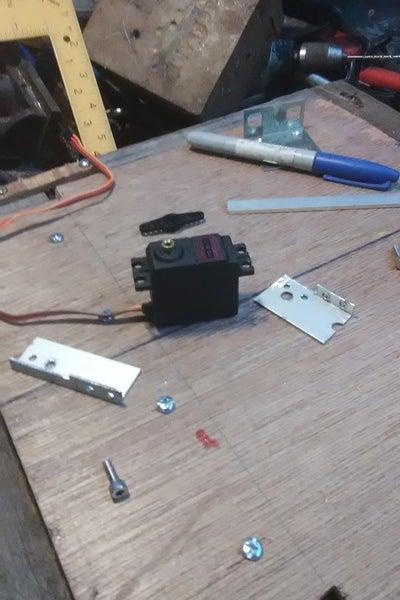
I used a MR-996 servo motor. It has a torque of : 9.4 kgf· cm (4.8 V ), or 11 kgf · cm (7.2 V) . This means that for a 20cm door below the pivot, the motor could lift 11kg/20 = 550g at 7.2V .
With counter weighted section above the pivot rod, the door could be heavier and/or longer. I used two large nuts and bolts as counterweights, shown in the pictures.
The servo comes with a plastic arm that fits on the servo’s splined output shaft. Cut one side of this arm with a sharp knife or wire cutters.
2. The lifting arm is made of two lengths of aluminium , the upper arm is an L bracket, the lower arm a flat piece of aluminium.
Attached diagrams show how to calculate the dimensions of each arm. The resulting dimensions are based on the frame width, “d”, and the position of the lifting point mounted on the door.
The upper arm has cutouts to so that the arm clears the servo motor when raising the door.
Step 4: Lock Solenoid and Door-open Support
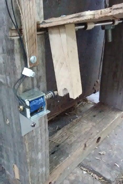
1. A solenoid mounted on the frame serves two purposes:
a) lock the door when it is shut , and
b) prevent the door from closing once opened.
The solenoid is driven via a FET from an output of the controller. It retracts for a few seconds while the door is in the process of opening or closing.
2. Secure a piece of timber as shown in the photo. It will be shorter than the frame width and mounted just below the pivot rod.
Source: Automatic Chicken Coop Door – Arduino Controlled.
- How is the door powered?
The door runs off 9Vdc and can be powered from a plugpack, a battery, or a solar panel to charge the battery. - Can the door be operated remotely?
Yes, the door can be opened or closed remotely at any time using the RF module. - What mechanism locks the door closed?
A 6V - 12V solenoid is used to lock the door when it is shut and to hold it in the open position. - How does the door pivot?
The door pivots upwards around a rod, similar to a garage door, and is counterweighted to reduce the torque needed. - What materials are suitable for the frame?
The frame should be sturdy and weatherproof; red-gum was used for sturdiness, while outdoor pine is easier to work with. - How often do settings need adjustment?
Since sunrise and sunset times change slowly, the controller settings only need to be adjusted once a week. - What is the range for adjustable opening times?
The opening time can be adjusted from 3am to 9am. - Does the design require complex sun tracking software?
No, this design uses manually adjustable open and close time settings instead of sun tracker software.