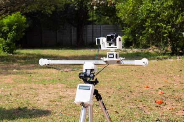
Are you fed up of shaky footage that ruins your video? In this Instructable I attempt to address this issue by building my own automated camera slider. I used the power of CAD and digital fabrication to create a robust gantry system that rolls along a length of square tubing. The gantry holds a pan and tilt mechanism that gives the user the ability to shoot from any angle.
The entire system is made using off the shelf parts such as stepper motors and Arduinos and it is designed to be easily transportable while being sturdy.
Follow on to create your own Automatic Arduino Powered Camera Slider and do drop a vote for this project in the “Automation Contest” if you enjoyed the project and decide to build your own version. I would love to see your own versions so do post your creations using the “I made it” section.
Step 1: Overview and Design Process

The automatic camera slider was designed in Autodesk’s free-to-use Fusion 360 3d modeling software. I began by importing the stepper motors into the design and built the pan and tilt mechanism around them. Next, I modeled the rail and made the two pieces that held the stepper motor and idle pulley on the ends of the rail. The design was made with structural stability and ease of assembly in mind. The gantry or the slider used regular bearings as wheels that kept contact with three faces of the square tubing. This allowed the gantry to roll smoothly without skewing.
Another goal while designing the automated slider mechanisms and parts was to keep the models as compact as possible and implement a modular design. This would allow the user to easily assemble and disassemble the slider and carry it around with them. This is one major point that traditional sliders tend to lack.
Finally, I designed an enclosure that would hold all the electronic components and a display that will display useful information.
Note:The parts are included in one of the following steps.
Step 2: Materials Needed
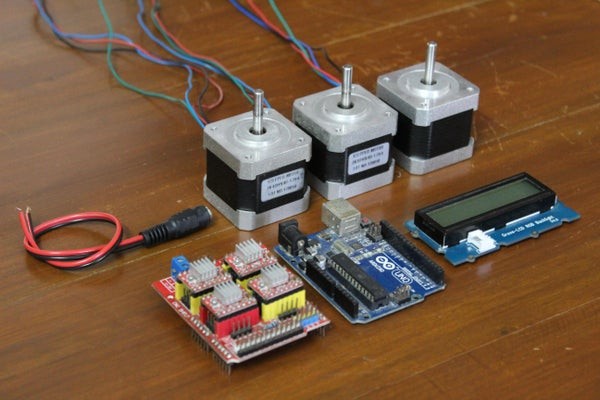
Here is the list of all the components and parts required to make your very own Automatic Arduino Powered Camera Slider. All parts should be commonly available and easy to find.
ELECTRONICS:
- Arduino Uno x 1
- NEMA17 Stepper Motor x 3
- CNC Shield x 1
- I2C LCD Screen x 1
- Jumper Wires (10 pieces)
- DC Connector x 1
HARDWARE:
- 20mm x 20mm square tubing (60 cm)
- GT2 Belt (2 m)
- Skateboard Bearings x 7(8x19x7 mm)
- M4 nuts and bolts
- 3D printer filament (in case you don’t own a 3D printer, there should be a 3D printer in a local workspace or the prints can be done online for quite cheap)
The approximate cost of all the parts is roughly 60 USD.
Step 3: Digitally Fabricated Parts

The parts required for this project had to be custom designed therefore a 3D printer was used to print them out. The prints were made at 60% infill, 4 perimeters, 0.4mm nozzle, and a layer height of 0.1mm with PLA. The color is of your choice. You can find the complete list of parts below along with the STLs to print your own version.
Note: From here on the parts will be referred to using the names in the following list.
- Slider Stepper Holder
- Idle Pulley Holder
- Gantry
- Stepper Pulley
- Idle Pulley
- Belt Holder x 2
- Tilt Bracket
- Pan Bracket
- Pan Stepper Holder
- Electronic Module Base
- Electronic Module Lid
- Electronic Module Holder
- Electronic Module Clamp
- Tripod Mount
- Floor Mount A
- Floor Mount B
In total there are 17 parts. The total printing time is about 30 hours.
Step 4: Building the Gantry and Preparing the Rail

Begin the assembly by cutting your square tubing to length. I used a 60 cm length of tubing, but this step depends on your needs. Once the tube is cut to length, drill two 4 mm holes on the rail. The holes should be made at the middle of the rail, 6 cm apart, and 0.5 cm from the bottom face of the square tubing. These holes will allow you to mount the slider onto a tripod.
Next, you can start assembling the gantry. The parts and pieces you will need are:
- 6 x Bearings
- 1 x Gantry
- 2 x Belt Holders
- 1 x Pan Stepper Holder
The gantry uses 2 bearings that roll along the top surface of the rail and 4 bearings (2 on each side surface of the rail) that prevent skewing. The 2 bearings for the top surface are connected along with the belt holders to the gantry piece using a single 4 mm nut and bolt for each side.
The other 4 bearings are mounted using the slots on the gantry piece so that you can adjust the position of the bearings such that the gantry rolls smoothly along the rail. Use 4 nuts and bolts to attach the four bearings along with the pan stepper holder.
Test the fit of the gantry on the rail and make sure it rolls smoothly.
Step 5: Slider Stepper Holder and Idle Pulley Holder
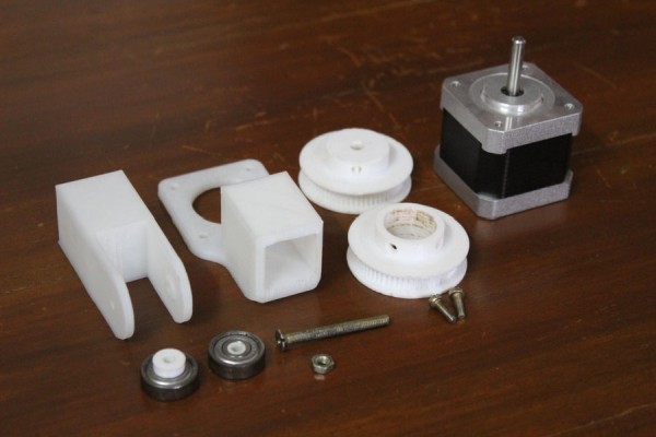
Once the gantry and rail are built, start assembling the stepper motor assemblies that move the gantry along the rail. The two assemblies consist of the drive assembly that holds the stepper motor and the idle assembly that holds the idle pulley. The parts and pieces required for this step are:
- 1 x Stepper motor
- 1 x Stepper Pulley
- 1 x Idle Pulley
- 1 x Slider Stepper Holder
- 1 x Idle Pulley Holder
- 2 x Bearings
To build the drive assembly, begin by mounting the stepper motor to the slider stepper holder using the provided bolts. Next, mount the stepper pulley onto the shaft of the stepper motor.
To build the idle assembly, embed 2 bearings on each side of the idle pulley. Pass a 4 mm bolt through the idle pulley holder and pulley such that the pulley is sandwiched between the two arms of the idle pulley holder.
Finally slide the two assemblies on each end of the rail. The fit is snug and might require a bit of sanding.
Step 6: Pan and Tilt Mechanism

Once the slider mechanism is built, you can begin to assemble the pan and tilt mechanism. The parts and pieces required for this are:
- 2 x Stepper Motors
- 1 x Bearings
- 1 x Pan Bracket
- 1 x Tilt Bracket
Begin by embedding a bearing into the hole on the pan bracket and attach the tilt bracket piece to the pan bracket using a nut and bolt passing through the hole on the tilt bracket and the bearing on the pan bracket. Use an additional nut or washer between the two brackets to create a slight gap between the two.
Mount the tilt stepper motor to the pan bracket using the given mounting bolt and slide the shaft into the hole on the tilt bracket. The fit is snug and does not require any extra reinforcement.
Finally, mount the pan motor to the gantry by sliding it in from one side and secure it using the bolts that were provided. Finish the assembly of the pan and tilt mechanism by pushing the pan bracket onto the pan stepper motor that is attached to the gantry. Once again the fit is snug and will not require any additional reinforcements.
Lastly, pass the belt around the two pulleys and push the ends through the belt holder pieces on each side of the gantry. You can use an additional clip or clamp to prevent the belt from loosening over time.
Step 7: Mounting the Action Camera

The mounting point for the camera is a universal connector. This will allow you to mount various types of action cameras such as GoPros and Dji’s Osmo Action. If your camera is slightly different, there are adapters that are easily available at electronics shops or online. To mount your camera or an adapter to the tilt bracket, pass a 4 mm nut and bolt through the connector and sandwich the camera’s connector in between and tighten it together with a bolt.
Source: Automatic Arduino Powered Camera Slider With Pan and Tilt