
Summary of Augment a Moog Etherwave Theremin
This article details a DIY project to hack a Moog Etherwave Theremin by integrating an Arduino-based "hackduino" circuit. The author built a custom microcontroller on a perfboard using an ATMega168 chip, a 7805 voltage regulator, and two RGB LEDs. Control voltages are tapped from the theremin's LM13700n OpAmp chip. The installation involves mounting the circuit inside the device, diffusing LED light with styrofoam spheres, and fitting a custom laser-cut acrylic top that is partially sanded for translucency.
Parts used in the Hack of Moog Etherwave Theremin:
- ATMega168 microcontroller (or ATMega328)
- 7805 voltage regulator
- 16MHz crystal oscillator
- Capacitors
- Perfboard
- Two RGB LEDs
- 30AWG wire
- Female header pins
- LM13700n chip (OpAmp)
- 1/4 inch clear plexi (acrylic)
- Styrofoam spheres
- Hot glue
- Sandpaper (emery paper)
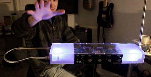
I’m going to go through my process of hacking a Moog Etherwave Theremin. I created a new acrylic top, partially sanded to be translucent in certain areas, and created my own circuit around an ATMega168 Arduino Bootloaded microcontroller which is stealing a control voltage from the theremin’s board and is driving 2 RGB LEDs which react to your playing.
In this project I embed what I call a hackduino which is an Arduino-compatible circuit, in this case built out by hand on perfboard. I have made an instructable specifically about building one of these yourself, which you can read here.
 Step 1: Build out the microcontroller circuit
I will be attaching the Arduino code to upload to your chip
I have built mine out on perfboard from radioshack. Reasons why I do not just use an Arduino board: This is cheap, and completely permanent. This entire circuit cost about $7 and is much smaller than an entire Arduino. I can permanently add components as I need to. I feel a sense of hacker legitimacy when I don’t spend $35 on the bulky blue board.
3. LEDs…. [next step]
Step 2: LEDs!
Step 3: Theremin hack!
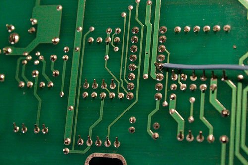
To get control voltages from the theremin itself, we are going to tap into one of OpAmp pins. I have had great success with soldering to pin 5 of the LM13700n chip on the board. However, this affords us access to just the amplitude (volume) antenna. I will find how to access the frequency antenna (pitch) and add that to this instructable when I do.
To get solder to this pin, remove the board from the theremin and flip it over. Attached is a picture of exactly what pin to solder to. Run the wire under the board toward the left side.
The next step in the hack is to attach female header pins to the row of breakouts located near the top left corner of the board when you are looking at it face on, right-side up (see images). The female headers will let us prototype easily.
Step 4: Get that board and LEDs in there!
The other nice trick I like to do is use styrofoam spheres to diffuse the LEDs. They can get quite bright, and the balls create a nice large object.
I used needle nose pliers to create a hole in each ball. Then just plopped the balls on top of each LED! So simple, cheap, and effective! yay efficiency!
 Step 5: Acrylic top time!
I used 1/4″ clear plexi for my top. Please post up any other materials you might find interesting/try out!
You will need approximately 2′ x 1′ piece of plexi, and using the Adobe Illustrator file I have attached, you shouldn’t have any problem at all. Laser the attached file (we have an Epilog 13 watt, I believe), and you’ll have a sweet top ready to go.
I decided I wanted both sides to be translucent, not clear (where the LEDs are). I drew a line at both sides, and with an exacto cut the paper along this line. I then take the paper off, and with a fine grit sandpaper (emory paper) go at the inside of the acrylic.
For more detail: Augment a Moog Etherwave Theremin
- How can I reduce the theremin's 12v DC output to 5v?
You must use a 7805 voltage regulator to lower the voltage. - What specific pin should I solder to on the theremin board?
You should solder to pin 5 of the LM13700n chip to access the amplitude antenna. - Can I use an ATMega328 chip instead of the ATMega168?
Yes, the provided code works for both ATMega168 and ATMega328 chips. - Why did the author choose to build the circuit on a perfboard instead of using a standard Arduino board?
The author chose perfboard because it is cheaper, smaller, completely permanent, and allows for adding components later. - What method does the author recommend for installing LEDs outside of a breadboard?
The author is a proponent of wirewrapping using 30AWG wire as it is easy, clean, lightweight, and permanent. - How can I diffuse the bright LEDs effectively?
You can create holes in styrofoam spheres with needle nose pliers and place them over the LEDs. - What material was used to create the new top for the theremin?
The author used a 1/4 inch clear plexi sheet cut to approximately 2 feet by 1 foot. - How did the author make parts of the acrylic top translucent?
The author sanded the inside of the acrylic with fine grit emery paper after cutting along drawn lines.
