
Summary of DIY Lithium Battery Charger Shield for Arduino
This article details a programmable single or multi-cell lithium battery charger shield for Arduino. It features an LCD and buttons to set cut-off voltages (2V–10V) and charge currents (50mA–1.1A). The design uses an LT1510 IC controlled by an Arduino UNO, with status monitoring via a Nokia 5110 LCD and ACS712-5A current sensor.
Parts used in the DIY Lithium Battery Charger Shield for Arduino:
- Arduino UNO
- LT1510 Constant Current/Constant Voltage Battery charger IC
- Nokia 5110 LCD
- ACS712-5A Hall Effect current sensor IC
- Q2 Mosfet
- Screw terminal block (two contact)
- Right angle 2mm JST-PH connector
- Resistors (R2, R3, R4, R7, R8, R24)
- Capacitor C5
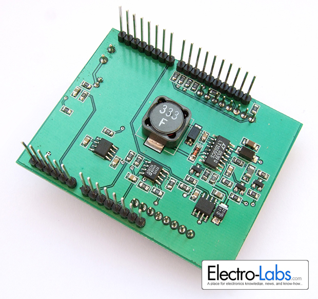
In this project, we are building a programmable single/multi cell lithium battery charger shield for Arduino. The shield provides LCD and button interface which let the user set the battery cut-off voltage from 2V to 10V and charge current from 50mA to 1.1A. The charger also provides the ability to monitor the battery status before and during charge.
The charger is based on LT1510 Constant Current/Constant Voltage Battery charger IC and controlled by Arduino UNO. The display on the shield is Nokia 5110 LCD which is very simple to use and still available on the market. There are two different battery connectors available on the shield, a two contact screw terminal block and a right angle 2mm JST-PH connector.
Circuit Design
The schematic of the project is drawn in SoloCapture, the schematic editor of SoloPCB tools. SoloCapture makes the schematic drawing process very easy and fast. You can download SoloPCB tools at Fabstream.com for FREE.
You can download the SoloPCB design files of the project by using the link below.
Please check out this video to see how to import the project libraries, open and synchronize the schematic and PCB files.
The lithium battery charger circuit is designed as an Arduino Shield. But the battery charger IC on the board can also work without MCU control. R3 and R4 sets the charge cut-off voltage, R2 ,R24 and C5 adjusts the charge current limit. With those passive component configurations, LT1510 can charge the battery and know when to stop. But we want to build a user programmable charger. So we had to take control of these functions. Anyway, when no code is present on Arduino, the charger has default cut-off voltage of 4.2V and maximum charge current of 1.1A.
Pulling VC pin of LT1510 to ground stops charging immediately. The pin 5 of Arduino assigned to drive Q2 Mosfet to stop charging when required. The battery voltage is divided by ten over R7 and R8 resistors and read by the A1 analog input. By using these two features, we can read the battery voltage and stop charging when the battery reaches a pre-determined voltage level.
In LT1510 datasheet, in addition to fixed resistor configuration, controlling the charge current by PWM method is also explained. Pin 6 of Arduino has PWM function and it is used for this purpose. Adjusting the PWM duty cycle easily adjusts the charge current. The current flowing to the battery is sensed by ACS712-5A Hall Effect current sensor IC and the sensor output is read by A0 analog input of Arduino. ACS712-5A outputs 0.185mV per 1A in addition to 2.5V. For example when the battery draws 1A, the sensor outputs 2.685V. To read the current more accurately, the internal voltage reference 1.1V is used so 10 bit ADC reading will fit between 0V and 1.1V at 1024 step resolution.
For more detail: DIY Lithium Battery Charger Shield for Arduino
- What voltage range can the user set for the battery cut-off?
The user can set the battery cut-off voltage from 2V to 10V. - How is the charge current adjusted in this project?
The charge current is adjusted using PWM on Pin 6 of the Arduino to control the duty cycle. - Which IC is used to sense the current flowing to the battery?
The ACS712-5A Hall Effect current sensor IC is used to sense the current. - Can the charger work without the Arduino code running?
Yes, the LT1510 IC can charge the battery without MCU control if passive components are configured correctly. - How does the system stop charging immediately when needed?
Pin 5 of the Arduino drives Q2 Mosfet to pull the VC pin of LT1510 to ground, stopping charging. - What internal reference is used to read the current more accurately?
The internal voltage reference of 1.1V is used so the 10 bit ADC reading fits between 0V and 1.1V. - Which display is used on the shield for the interface?
A Nokia 5110 LCD is used which is simple to use and available on the market. - What are the default settings if no code is present on the Arduino?
The default cut-off voltage is 4.2V and the maximum charge current is 1.1A.
