Summary of Audio Visualizer With an LCD Display
This article guides readers on building a simple audio visualizer using an Arduino UNO. The project converts sound waves into visual bar graphs displayed on an LCD screen. It covers the necessary components, wiring diagrams, and the specific C++ code required to process analog sensor data and render dynamic characters based on volume levels.
Parts used in the Audio Visualizer:
- 16x2 LCD display
- Arduino UNO (or Nano)
- Two 1kΩ resistors
- LM393 Sound Sensor Module
- Jumper Cables and Breadboard
- A computer for uploading the code
People love listening to music. It is as they say, music reflects our mood. And it is a spectacle to see music become ‘alive’ right before our eyes. Well, that’s what music visualization does.
According to Wikipedia, music visualization “generates animated imagery based on a piece of music. The imagery is generated and rendered in real time and is synchronized with the music we play.”
Music visualization is greatly seen on EDM concerts, where artists team up with VJs (or video jockeys) to create visual spectacles, that can attract and mesmerize the audience. This can be done with video editing and effects software such as Davinci Resolve Fusion and Adobe After Effects. However, this can also be achieved using hardware.
In this Instructable we’re gonna create a simple and easy-to-make audio visualizer using an Arduino UNO, a sound sensor or a microphone, and a 16×2 LCD display. So without further ado, let’s get started
Supplies
Here are the list of components required for creating this project
- 16×2 LCD display
- Arduino UNO (or Nano)
- Two 1kΩ resistors
- LM393 Sound Sensor Module
- Jumper Cables and Breadboard
- A computer for uploading the code
That’s it. No other components are required.
All the items are easily available on Amazon or any other shopping app. Or you can just go to your nearest electronics dealer to get your components.
Step 1: Connecting Each Component
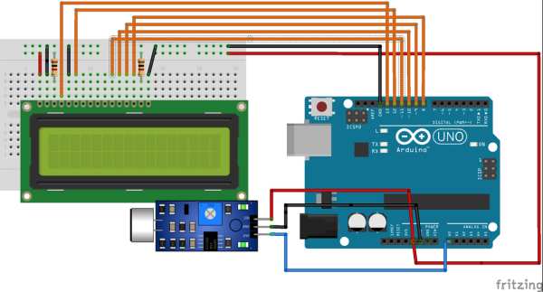
Here are the following connections for both LCD and Sound Sensor Module to the Arduino UNO. This breadboard diagram was made on a software called Fritzing.
I won’t be going on too long with the technical details here, just where you need to connect and why.
LCD Connections
- VSS and VDD to 5V and GND respectively, to power the LCD.
- V0 connected to a 1k resistor and then to GND. We are not changing the contrast of the LCD here, so the LCD will show the characters clearly.
- RS (Register Select) to pin 13. It is configured to give value HIGH so that Data Register is selected (you don’t need to know what a Data Register does, just that it helps in transferring data to the LCD)
- R/W (Read/Write) to GND. We configure the R/W pin to value LOW so that we can write data to the LCD.
- E (Enable) to pin 12. This is used to latch (keep all the data coming from the Arduino to the data pins.
- pins D4-D7 are connected to pins 11 to 8 respectively. They are the data pins which will transfer data from Arduino to the LCD display
- LED+ is connected to 1k resistor and then to 5V, and LED- to GND. This is for the LED backlight, which will cause the LCD display to glow.
Sound Sensor connections
The Sound Sensor Module detects the sound via a microphone and feeds into an op-amp (LM393-dual comparator). It has 4 pins
- VCC – Powered by +5V
- GND – Ground
- Analog pin (AO) – Analog output connected to analog input of microcontroller
- Digital pin (DO) – Digital output connected to digital input of microcontroller
The four pins are connected to Arduino UNO as follows
- VCC to 5V
- GND to GND
- AO to analog pin A0
- DO to nothing (here we are not using digital output)
After following the steps exactly as mentioned, you are good to upload the program.
Step 2: Uploading the Program

The above image is the schematic of the circuit, also made on Fritzing.
I have created a program for the same circuit. If you have followed the exact steps for building the circuit, you can upload the code directly to the Arduino Board, or you need to change some parameters according to your connections.
Following is the code for my circuit.
#include <LiquidCrystal.h>
LiquidCrystal lcd(13,12,11,10,9,8);
int soundsensor = A0;
float t = 25;
float t1 = 5;
void setup() {
// put your setup code here, to run once:
pinMode(soundsensor, INPUT);
Serial.begin(9600);
lcd.begin(16,2);
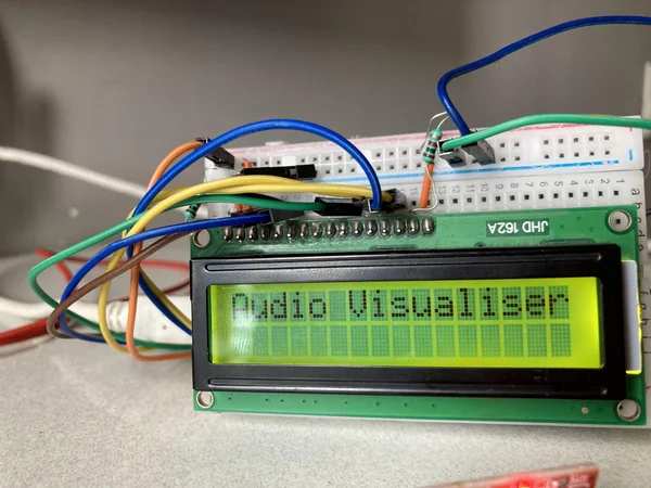
lcd.setCursor(0,0);
lcd.print("Audio Visualiser");
delay(2000);
}
void loop() {
// put your main code here, to run repeatedly:
long sum=0;
int sensorVal= analogRead(soundsensor);//Input from soundsensor
Serial.println(sensorVal);
for(int i=0;i<100;i++){
sum+=sensorVal;
}
sum=sum/100;
/* here we are comparing the soundsensor values with the pre determined values (selected at random). If it goes above the pre dertermined value, the character will be displayed*/
if(sum>195){
lcd.clear();
lcd.setCursor(0,1);
lcd.print("#");
lcd.setCursor(0,0);
lcd.print("##");
delay(t);
}
else{
lcd.clear();
lcd.setCursor(0,1);
lcd.print(" ");
lcd.setCursor(0,0);
lcd.print("#");
delay(t1);
}
if(sum>200){
lcd.clear();
lcd.setCursor(0,1);
lcd.print("##");
lcd.setCursor(0,0);
lcd.print("####");
delay(t);
}
else{
lcd.clear();
lcd.setCursor(0,1);
lcd.print("#");
lcd.setCursor(0,0);
lcd.print("##");
delay(t1);
}
if(sum>205){
lcd.clear();
lcd.setCursor(0,1);
lcd.print("###");
lcd.setCursor(0,0);
lcd.print("#####");
delay(t);
}
else{
lcd.clear();
lcd.setCursor(0,1);
lcd.print("##");
delay(t1);
}
if(sum>210){
lcd.clear();
lcd.setCursor(0,1);
lcd.print("####");
lcd.setCursor(0,0);
lcd.print("######");
delay(t);
}
else{
lcd.clear();
lcd.setCursor(0,1);
lcd.print("##");
delay(t1);
}
if(sum>220){
lcd.clear();
lcd.setCursor(0,1);
lcd.print("#####");
lcd.setCursor(0,0);
lcd.print("########");
delay(t);
}
else{
lcd.clear();
lcd.setCursor(0,1);
lcd.print("###");
delay(t1);
}
if(sum>230){
lcd.clear();
lcd.setCursor(0,1);
lcd.print("#######");
lcd.setCursor(0,0);
lcd.print("#########");
delay(t);
}
else{
lcd.clear();
lcd.setCursor(0,1);
lcd.print("###");
delay(t1);
}
if(sum>240){
lcd.clear();
lcd.setCursor(0,1);
lcd.print("########");
lcd.setCursor(0,0);
lcd.print("#########");
delay(t);
}
else{
lcd.clear();
lcd.setCursor(0,1);
lcd.print("##");
delay(t1);
}
if(sum>260){
lcd.clear();
lcd.setCursor(0,1);
lcd.print("############");
lcd.setCursor(0,0);
lcd.print("##########");
delay(t);
}
else{
lcd.clear();
lcd.setCursor(0,1);
lcd.print("#");
delay(t1);
}
if(sum>280){
lcd.clear();
lcd.setCursor(0,1);
lcd.print("##############");
lcd.setCursor(0,0);
lcd.print("############");
delay(t);
}
else{
lcd.clear();
lcd.setCursor(0,1);
lcd.print(" ");
delay(t1);
}
Serial.println(sum);
}
You can also modify the code to obtain different results. Feel free to post your modifications in this Instructable
If you have any problems in uploading the code from the code box, I have also attached the code file, which contains the same program as in the code box.
Step 3: My Hardware Works!
I will explain the working in a simpler way.
When music is played from the speakers, the microphone picks up the sound and sends it to the op-amp. The op-amp (or operational amplifier, if you didn’t know that) works as a comparator (a device which compares two values and sends an output if one is greater than the other), and sends the output to the analog port in the Arduino UNO
We can access the output values from the Serial Monitor for analysis and use the potentiometer (soldered in the module itself) to change the sensitivity (as per required).
I have programmed these values in such a way that if the input goes above a certain value, the LCD will display the characters and it will increase in a bar like shape. The characters can be customized as per the user.
Well, a person can understand only a little bit by explaining with words, so I have uploaded a video too.
Step 4: Everything Has an End
Congratulations for reaching this far!
It is as they say, if there is a beginning, there will be an end, and this Instructable has to end (or else you will get really board reading this). And while this visualizer may not be perfect, it is simple and you can make it in 10 minutes (half an hour, tops). And hey, it is as they say, a simple solution may or may not be perfect.
Now that I have shown you how the audio visualizer works, it is now up to you to build and modify the circuit. You can add another LCD display (just to give that visualizer feeling), or change it altogether (bigger the display, better the visualization).
There are endless ideas for modification, and all of this can be saved for a later date. I hope that all of you enjoyed reading this Instructable. If you want more of these Instructables, please do share it with your friends and colleagues, and encourage them to build this circuit.
Source: Audio Visualizer With an LCD Display
- What is music visualization?
It generates animated imagery based on a piece of music that is rendered in real time and synchronized with the music played. - How do I connect the V0 pin of the LCD?
The V0 pin is connected to a 1k resistor and then to GND to ensure the LCD shows characters clearly without changing contrast. - Which pins are used for the Sound Sensor connections?
VCC connects to 5V, GND to Ground, AO to analog pin A0, and DO is left unconnected in this specific project. - Can I modify the sensitivity of the sound sensor?
Yes, you can use the potentiometer soldered in the module itself to change the sensitivity as per your requirements. - How does the op-amp function in this circuit?
The op-amp acts as a comparator which compares two values and sends an output to the analog port if one value is greater than the other. - What happens when the input value goes above a certain threshold?
The LCD will display characters that increase in a bar-like shape depending on the specific value received from the sensor. - Is it possible to customize the characters on the display?
Yes, the characters displayed on the LCD can be customized as per the user's preference by modifying the code. - How long does it take to build this project?
You can make this simple solution in about 10 minutes, or half an hour at the most.