Summary of ATtiny85 EMF Detector
This article provides a tutorial on building an EMF detector using an Attiny85 microcontroller instead of an Arduino. It explains the concept of electromagnetic fields and lists necessary components like LEDs, resistors, and a battery. The guide details circuit assembly on a breadboard and protoboard, provides the source code for detecting field strength via LED indicators, and outlines the specific steps to install an older version of the Arduino IDE (1.0.6) required to program the Attiny85 chip.
Parts used in the EMF Detector:
- Protoboard
- Breadboard
- Attiny85 X 1
- Green leds X 2
- Yellow led X 1
- Red led X 1
- CR2025 Battery X 1
- CR2025 Battery case X 1
- 40 Ohm resistors for leds X 4
- 1 MOhm resistor for probe X 1
- Jumper wires
Story
This is a simple tutorial to create an EMF detector. You can use Arduino for this job, but is better use a microcontroller called Attiny85. It is possible program it throe the Arduino interface.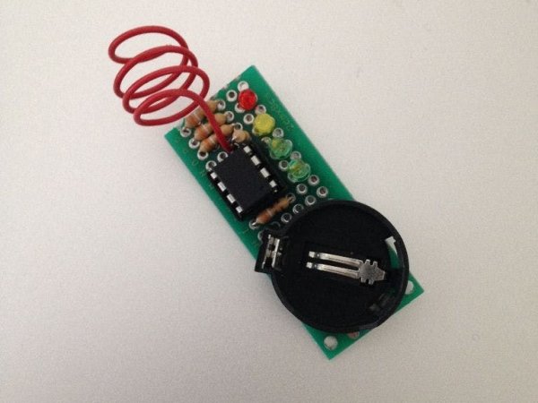
What is a Magnetic Field [from Wikipedia]
An electromagnetic field (also EMF or EM field) is a physical field produced by electrically charged objects. It affects the behavior of charged objects in the vicinity of the field. The electromagnetic field extends indefinitely throughout space and describes the electromagnetic interaction. It is one of the four fundamental forces of nature (the others are gravitation, weak interaction and strong interaction).
The field can be viewed as the combination of an electric field and a magnetic field. The electric field is produced by stationary charges, and the magnetic field by moving charges (currents); these two are often described as the sources of the field. The way in which charges and currents interact with the electromagnetic field is described by Maxwell’s equations and the Lorentz force law. From a classical perspective in the history of electromagnetism, the electromagnetic field can be regarded as a smooth, continuous field, propagated in a wavelike manner; whereas from the perspective of quantum field theory, the field is seen as quantized, being composed of individual particles.
The materials of this project are:
- Protoboard
- Breadboard
- Attiny85 X 1
- Green leds X 2
- Yellow led X 1
- Red led X 1
- CR2025 Battery X 1
- CR2025 Battery case X 1
- (optional) 40 Ohm resistors for leds X 4
- 1 MOhm resistor for probe X 1
- Jumper wires
Many of these components are in this KIT
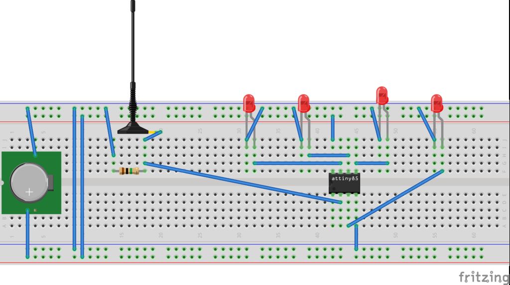
Step 1: The circuit
First step is create a circuit on the breadboard. Use a breadboard like in photo and try the circuit before solder it on protoboard. After the test you can use a protoboard to connect the attiny85 to leds and antenna.
For upload the code on Attiny85 you can use this shield and a programmer, or your Arduino UNO.
Step 2: The code
See the code also on GitHub: https://github.com/masteruan/Attiny85_EMF
// EMF Detector Attiny85 and 4 led v1.0// 23.10.2015// original code/project by Aaron ALAI – [email protected]// modified for use by Giovanni Gentile – [email protected]
#define NUMREADINGS 15 // Number of readings
int senseLimit = 15; // Raise this num to decrease sensitivity int val = 0; int antenna = A2;
int LED[] = {2,0,1,3}; // After verify the position of red green and yellow leds
// Variables for smoothing
int readings[NUMREADINGS];
int index = 0;
int total = 0;
int averange = 0;
void setup() {
pinMode(2, OUTPUT);
pinMode(0, OUTPUT);
pinMode(1, OUTPUT);
pinMode(3, OUTPUT);
pinMode(A2, INPUT);
// Test leds on start
for (int i=0; i<4; i++) {
digitalWrite(LED[i],HIGH);
delay(500);
}
for (int i=0; i<4; i++) {
digitalWrite(LED[i],LOW);
}
// Initialize all the readings
for (int i = 0; i < NUMREADINGS; i++) {
readings[i] = 0;
}
}
void loop() {
int val = analogRead(antenna);
if(val >= 1){
val = constrain(val, 1, senseLimit); // turn any readings higher than the senseLimit into the senseLmit
value val = map(val, 1, senseLimit, 1, 1023); // remap the values
total -= readings[index]; // subtract the last reading
readings[index] = val; // read from the sensor
total+= readings[index]; // add the reading to the total
index = (index + 1); // advance to the next index
if (index >= NUMREADINGS) index = 0;
averange = total / NUMREADINGS;
if (averange > 50) {
digitalWrite(2,HIGH); }
else {
digitalWrite(2,LOW); }
if (averange > 350) {
digitalWrite(0,HIGH); }
else {
digitalWrite(0,LOW); }
if (averange > 750) {
digitalWrite(1,HIGH); }
else {
digitalWrite(1,LOW); }
if (averange > 950) {
digitalWrite(3,HIGH); }
else { digitalWrite(3,LOW); }
}
}
Step 3: Install Arduino IDE and programming Attiny
Go to www.arduino.cc
Go to Download (https://www.arduino.cc/en/Main/Software)
And select the previous installation of Arduino IDE 1.0.6. This is very IMPORTANT because with the new version of Arduino IDE is impossible to program the Attiny85. After the installation of attiny85 package you can select the Attiny models.
After installation of IDE you can programming the Attiny85 by your Arduino UNO. Then following this tutorial https://www.instructables.com/id/How-to-program-the…
For more detail: ATtiny85 EMF Detector
- What is the best microcontroller for this project?
The article states it is better to use an Attiny85 than an Arduino. - How can I program the Attiny85?
You can program it through the Arduino interface using an Arduino UNO or a shield with a programmer. - Which version of Arduino IDE should I install?
You must select and install the previous installation of Arduino IDE 1.0.6 because newer versions cannot program the Attiny85. - What is the purpose of the antenna pin A2?
The antenna connected to A2 is used to read analog values from the sensor to detect electromagnetic fields. - How does the code determine LED activation?
The code compares the average reading against thresholds (50, 350, 750, 950) to turn specific LEDs HIGH or LOW. - Can I test the circuit before soldering?
Yes, you should try the circuit on a breadboard first before connecting it to a protoboard. - What happens if the sensor reading exceeds the senseLimit?
The value is constrained so that any readings higher than the senseLimit are turned into the senseLimit value. - Why is smoothing used in the code?
The code uses an array of 15 readings to calculate an average, which smooths out the data from the sensor.