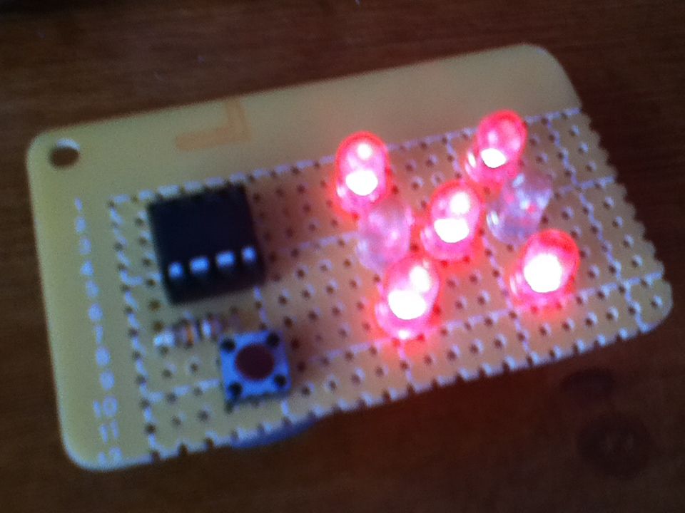
If you have looked at my 5 LED ATtiny85 POV display, we programmed the ATtiny with the Arduino. (If you haven’t seen it, click here) We will be doing the same thing for this LED Dice project.
The total parts cost for this project is about $5-$10. (Not including the Arduino board and the tools.)
It is super simple to make, so don’t worry if you don’t have a lot of programming/ electronics experience.
This is a contest entry for the LED Contest with Elemental LED, so don’t forget to vote for me! 😉
Step 1: Parts list
Here’s all the stuff you need. You can get it all for 5-10 bucks if you buy from Mouser/Digi-Key.
Parts:
1x ATtiny85/45/25 (8 pin DIP)
1x 8 pin DIP socket
1x Tactile pushbutton switch
1x 10K Ohm resistor
7x LEDs (I used clear, high-brightness red. We will be powering this with a 3 volt battery pack, so make sure you choose something that can handle that much power)
1x 2 AA/AAA battery pack (could also be a 3 volt CR2032 coin cell battery, just make sure whatever pack you choose that it’s 3 volts)
Some perfboard
Batteries that go with your battery pack
Some wire
Step 2: How it works
At this point, you might be thinking that the ATtiny85 does not have enough input/output pins to drive 7 LEDs and read the input of a pushbutton.
If you thought this, you would be right, but there is a way around this.
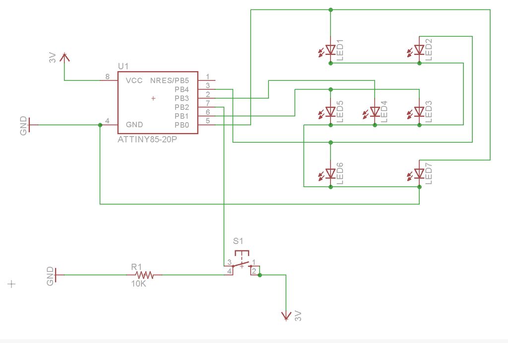
If you look at a 6 sided die, you might notice that there are never 2 dots that aren’t diagonal or across from each other that are not there at the same time (except for the middle one). That means that we can connect the top left LED to the bottom right LED, the middle left LED to the middle right LED, and the bottom left LED to the top right LED.
So now we only need 4 pins to control all of the LEDs (the 3 pairs of LEDs and the single middle one). That means we have one pin left over to read the push button. Perfect!
Step 3: Program the ATtiny MCU
If you read my Instructable on the 5 LED POV display, they you probably already know how to do this. For those of you that don’t, here is a guide.
This is the code that you need to upload to the ATtiny:
int pinLeds1 = 3;
int pinLeds2 = 2;
int pinLeds3 = 1;
int pinLed4 = 0;
int buttonPin = 4;
int buttonState;
long ran;
int time = 2000;
void setup ()
{
pinMode (pinLeds1, OUTPUT);
pinMode (pinLeds2, OUTPUT);
pinMode (pinLeds3, OUTPUT);
pinMode (pinLed4, OUTPUT);
pinMode (buttonPin, INPUT);
randomSeed(analogRead(0));
}
void loop()
{
buttonState = digitalRead(buttonPin);
if (buttonState == HIGH){
ran = random(1, 7);
if (ran == 1){
digitalWrite (pinLed4, HIGH);
delay (time);
}
if (ran == 2){
digitalWrite (pinLeds1, HIGH);
delay (time);
}
if (ran == 3){
digitalWrite (pinLeds3, HIGH);
digitalWrite (pinLed4, HIGH);
delay (time);
}
if (ran == 4){
digitalWrite (pinLeds1, HIGH);
digitalWrite (pinLeds3, HIGH);
delay (time);
}
if (ran == 5){
digitalWrite (pinLeds1, HIGH);
digitalWrite (pinLeds3, HIGH);
digitalWrite (pinLed4, HIGH);
delay (time);
}
if (ran == 6){
digitalWrite (pinLeds1, HIGH);
digitalWrite (pinLeds2, HIGH);
digitalWrite (pinLeds3, HIGH);
delay (time);
}
}
digitalWrite (pinLeds1, LOW);
digitalWrite (pinLeds2, LOW);
digitalWrite (pinLeds3, LOW);
digitalWrite (pinLed4, LOW);
}
Step 4: Breadboard it!
Step 5: Solder it!
Now you can solder it onto your perfboard, if you would like. Be careful though, it gets kind of trick with all the LED wires/leads crossing, make sure they are not touching, or else your dice will not work.
Also, make absolutely sure that you connect/arrange the LEDs correctly, or else the LEDs will not light up the right way.
Sorry I couldn’t take pictures of the soldering process, I made this Instructable after I completely finished the dice.


