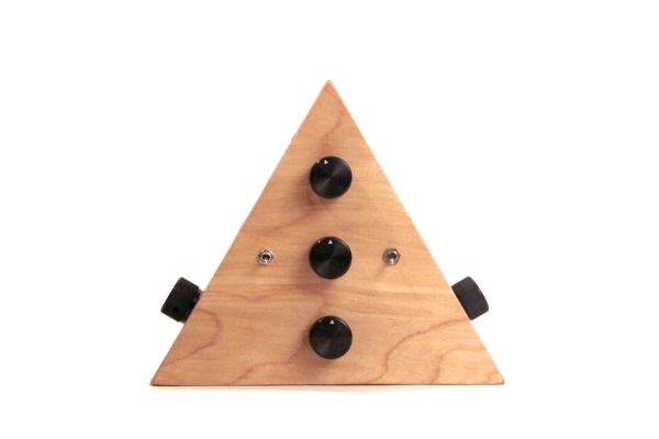
This Arduino-powered vocal effects box pitch shifts and distorts incoming audio signals to produce a wide variety of vocal effects. This project is my first experiment with real-time digital signal processing using Arduino. It samples an incoming microphone signal at a rate of about 40kHz, manipulates the audio digitally, and then outputs 8 bit audio at 40kHz. To minimize the amount of computation required by the Arduino, I used a technique called granular synthesis to manipulate the incoming audio signal. Essentially, as audio comes into the Arduino it gets cut up and stored as small (millisecond or microsecond sized) samples called “grains.” These grains are then individually manipulated and played back; they may be lengthened or shortened, stretched or compressed, played back in reverse, copied several times, or mixed with other grains. You can hear a (somewhat creepy) audio sample from the effects box below:
Granular synthesis creates a unique type of distortion caused by discontinuities between individual grains in the outgoing signal. Sometimes this distortion creates an effect I can only describe as a “ripping” sound, other times it introduces new frequencies into the audio that were not present before. Here is an example by Aphex Twin, the granular synthesis is especially prominent in the bridge at around 3min in. Another example of granular synthesis, this time applied to vocals for pitch shifting and textural effects, is from Paul Lansky. My favorite thing to do with this effects box is to use subtle pitch shifting to achieve an androgynous vocal sound, I got the idea for the project after listening to copious amounts of Fever Ray this past winter, you can hear how she pitch shifts her voice to sound somewhat masculine at times.
PARTS LIST
(1x) Arduino Uno REV 3 Radioshack 276-128
(7x) 10K Ohm 1/4-Watt Carbon Film Resistor (2 packages) Radioshack #271-1335
(9x) 20K Ohm 1/4-Watt Carbon Film Resistor (2 packages)
(1x) 1K Ohm 1/4-Watt Carbon Film Resistor Radioshack 271-1321
(1x) 50K-Ohm Linear-Taper Potentiometer Radioshack #271-1716
(1x) 10KOhm Audio Control Potentiometer with SPST Switch Radioshack #271-215 (this will be used to control volume and turn the device on/off)
(5x) 0.25″ Knurled Knob Radioshack 274-424
(2x) 9V Alkaline Battery Radioshack #23-866
(2x) Heavy-Duty 9V Snap Connectors Radioshack #270-324
(1x) PC Board with Copper Radioshack #276-147
(1x) SPST PC-Mountable Submini Toggle Switch Radioshack #275-645
(2x) Male Header Pins Jameco 103393
(3x) 8 pin socket Radioshack 276-1995
(1x) TL082 Wide Dual JFET Input Op Amp Radioshack 276-1715
(3x) 100K Ohm 1/4-Watt Carbon Film Resistor (1 package) Radioshack 271-1347
(1x) 10uF electrolytic capacitor
(1x) 47nF capacitor
(3x) 0.1uf capacitor Radioshack 55047557
(2x) 1M-Ohm Linear Taper Potentiometer Radioshack 271-211
(1x) 1MOhm logarithmic potentiometer
(1x) 2kOhm 1/4-Watt Carbon Film Resistor
(1x) male header pins Jameco 103393
(1x) 10K-Ohm Linear-Taper Potentiometer Radioshack 271-1715
(1x) DPDT Flatted Metal Lever Toggle Switch Radioshack 275-636
(2x) 1/4″ stereo jack Radioshack 274-141 or Radioshack 274-312
(2x) 5mm High-Brightness White LED (1 package) Radioshack 276-017
(2x) 100 ohm 1/4W 5% Carbon Film Resistor Radioshack 271-1311
(2x) TS922IN Dual Op Amp Digikey 497-3049-5-ND (one TS924 would also work, but they are not available on digikey at the moment)
Additional Materials:
22 Gauge Wire Radioshack #278-1224
Solder Radioshack #64-013
sand paper
plywood
wood glue
hot glue
screws
Download Arduino IDE
Step 1: Schematic
I’ve broken the schematic into three parts so it is easier to understand.
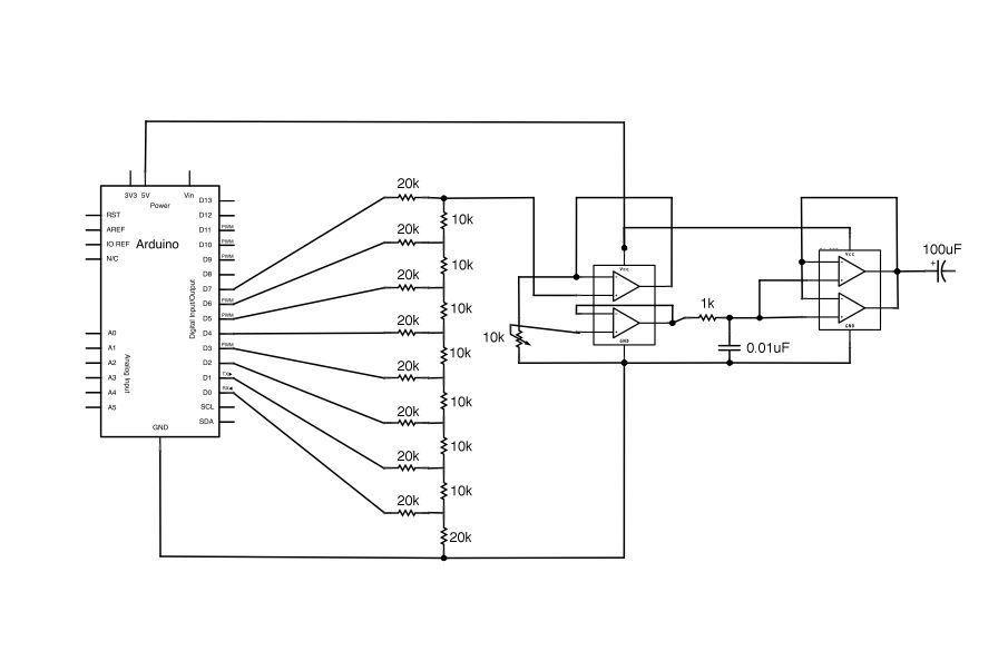
The first schematic shows the audio out circuit. This project outputs audio through an 8 bit R2R digital to analog converter through Arduino digital pins 0-7. This signal is sent through an amplifier, a low pass filter, and a volume control pot before being sent out to speakers.
The second schematic shows the mic input circuit. The line in the from the mic is sent through an amplifier and a DC offset circuit before being sent into the Arduino via analog input pin A0.
The third schematic shows how all the controls of the effects box are connected to the Arduino. There are two LED indicators in this project: one clipping indicator and one output indicator. Three pots on the device control grain size, pitch, and wet/dry mix and a switch controls the direction of sample playback (forward or reverse).
Step 2: Header Pins
Solder header pins to your protoboard so that you can snap the Arduino directly to the board. Unfortunately the spacing between digital pins 7 and 8 on the Arduino is not the standard 2.54mm, so I’ve found that it’s best to try to avoid using these pins if possible (analog pins can also be used as digital I/O). If you have to use them, try finding long header pins which you can bend into shape (fig 4- from another project).
Step 3: DAC: Part 1
Solder eight 20kOhm resistors to Arduino pins D0-D7 as shown in the images above.
Step 4: DAC: Part 2
Solder seven 10kOhm resistors in between each of the 20kOhm’s you just soldered. Add an additional 20kOhm resistor to the 20kOhm connected to Arduino D0 (the bottom of the ladder).
Major Components in Project
(1x) Arduino Uno REV 3 Radioshack 276-128
(7x) 10K Ohm 1/4-Watt Carbon Film Resistor (2 packages) Radioshack #271-1335
(9x) 20K Ohm 1/4-Watt Carbon Film Resistor (2 packages)
(1x) 1K Ohm 1/4-Watt Carbon Film Resistor Radioshack 271-1321
(1x) 50K-Ohm Linear-Taper Potentiometer Radioshack #271-1716
(1x) 10KOhm Audio Control Potentiometer with SPST Switch Radioshack #271-215 (this will be used to control volume and turn the device on/off)
(5x) 0.25″ Knurled Knob Radioshack 274-424
(2x) 9V Alkaline Battery Radioshack #23-866
(2x) Heavy-Duty 9V Snap Connectors Radioshack #270-324
(1x) PC Board with Copper Radioshack #276-147
(1x) SPST PC-Mountable Submini Toggle Switch Radioshack #275-645
(2x) Male Header Pins Jameco 103393
(3x) 8 pin socket Radioshack 276-1995
(1x) TL082 Wide Dual JFET Input Op Amp Radioshack 276-1715
(3x) 100K Ohm 1/4-Watt Carbon Film Resistor (1 package) Radioshack 271-1347
(1x) 10uF electrolytic capacitor
(1x) 47nF capacitor
(3x) 0.1uf capacitor Radioshack 55047557
(2x) 1M-Ohm Linear Taper Potentiometer Radioshack 271-211
(1x) 1MOhm logarithmic potentiometer
(1x) 2kOhm 1/4-Watt Carbon Film Resistor
(1x) male header pins Jameco 103393
(1x) 10K-Ohm Linear-Taper Potentiometer Radioshack 271-1715
(1x) DPDT Flatted Metal Lever Toggle Switch Radioshack 275-636
(2x) 1/4″ stereo jack Radioshack 274-141 or Radioshack 274-312
(2x) 5mm High-Brightness White LED (1 package) Radioshack 276-017
(2x) 100 ohm 1/4W 5% Carbon Film Resistor Radioshack 271-1311
(2x) TS922IN Dual Op Amp Digikey 497-3049-5-ND (one TS924 would also work, but they are not available on digikey at the moment).
For more detail: Arduino-Powered Vocal Effects Box