This page maintains the necessary documentation (hardware & software) for recreating the Solar Hardware Module (“Solar Module”) using either Arduino UNO or TI Launchpad.
Prior to creating the solar module, we performed several experiments using a custom built solar panel fixture. For more information on the solar panel fixture, see link below. Solar Panel Fixture
Solar Module
A Solar Module hardware was designed to provide hands-on experience for beginning undergraduate engineering students. Hands-on experience includes programming hardware for data collection and sampling, and setting up and programming simple sensor networks for cooperative sensing. Finally, students learn statistical methods to analyze the collected data.
Two versions of the solar module are built: Arduino-based and MSP430 Launchpad-based. Arduino UNO was selected for its wide community support and ease of hardware/software development. MSP430-based solution was
Solar Sensor Module – MSP430-based, Wireless (In Progress)
MSP430-based design was developed for its low power consumption and low cost. Hence the TI Launchpad was considered. In addition, MSP430-based wireless module was also available which made the Launchpad even more attractive due to uniformity in the hardware and the development environment.
The wireless sensor module is based on the Texas Instrument (TI) Launchpad and the Wireless Development Tool. Both boards are based on the MSP430 low power microcontroller and can be programmed using a single development tool. The wireless interface allows biderational communication between the sensor and the gateway/host computer. The sensor senses the output of a small solar cell on board. The small solar cell is connected to a load, which is emulated by a digital potentiometer. The voltage across the digital potentiometer is sampled and digitized by the internal ADC on the MSP430 on the Launchpad. Finally, the sample is then transmitted to the gateway via the wireless interface.
The wireless interface communicates with the host computer using the CC2500 chip, operating in the 2.4 GHz ISM band. The digital potentiometer (Maxim DS1803) is controlled by the MSP430 via the I2C interface. The entire sensor node is powered by a single 9V battery.
On the host computer, transmitted sensor data is received by the USB dongle (part of the TI Wireless Development Tool) and converted back to serial data. The USB port is emulating a serial terminal. The serial data is then read and processed by student-written MATLAB code.
Information on the Wireless Solar Module is below.
Hardware
TI MSP430 Launchpad — information on the Launchpad.
TI Wireless Development Tool — information on the wireless interface hardware.
Schematic — schematic for constructing the wireless sensor module.
Block Diagram — block diagram for the wireless sensor module.
BOM — bill of materials for the wireless sensor module.
Software
Programming using Energia software. Code for the Launchpad.
Code for the Wireless Module.
MATLAB Class.
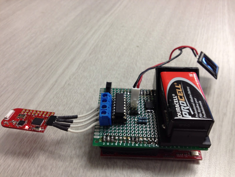
Picture of the MSP430 Wireless Solar Sensor
Launchpad is on the bottom. The board on the top is a custom daughter board/shield containing solar cell, digital potentiometer, 9V battery, and connection to wireless module.
Side view 1.
Side view 2.
Solar Sensor Module – Arduino UNO-based (Completed)
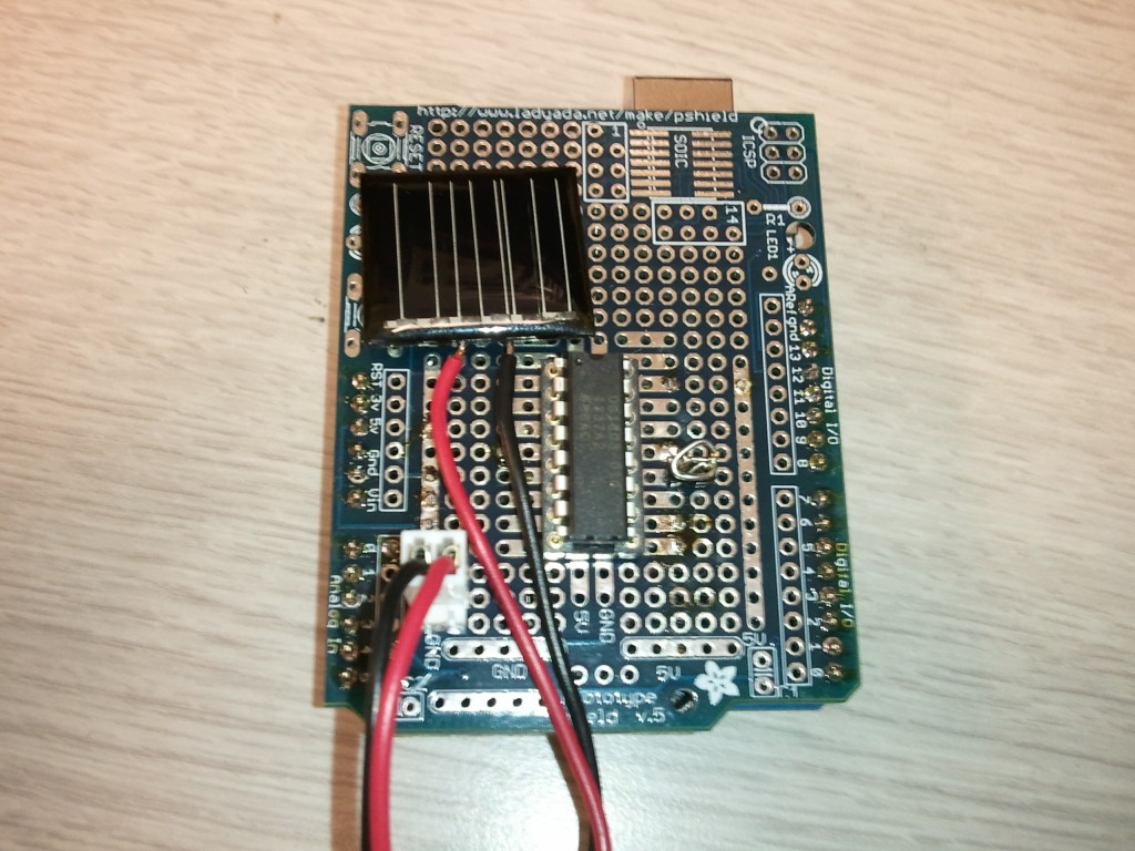
An Arduino-based solar sensor module was built so students can obtain hands-on experience with controlling hardware, taking measurements from hardware, and perform analysis on measured data.
The hardware module consists of Arduino UNO board, small solar cell, and a digital potentiometer (load for the solar cell). The potentiometer is controlled by the Arduino through I2C.
The Arduino communicates with the host computer through a serial interface emulated on the USB port. The Arduino is also powered from the USB port and it runs the Arduino server code (adiosrv.ino). The server code is based on the code available here.
For more detail: Solar Module Using Either Arduino UNO or TI Launchpad


