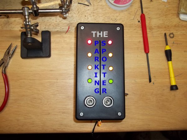
For my first instructable, I’d like to present The Parking Spotter. This is not a new concept, I know. However, this build was done specifically to suit my needs/wants/materials already in my possession. Typically, a project begins with an idea, parts are then gathered, and the building commences. In my case I looked around at the parts and material that I had on-hand, browsed Instructables (a daily occurrence), and found inspiration from others. I shouldn’t fail to mention the site of wooden saw horses in front of my sister-in-laws $30k car to protect the $200 bicycle!! So, let’s dive in!
Tools:
Soldering iron, solder & fume extractor
Drill or drill-press
Appropriate drill bit for your LED holders
5/8″ drill bit for the sensor holes
Screwdriver for the enclosure
Third-hand
And, anything that you feel you need to make your task easier.
I am going to assume that you are, at least, familiar with the Arduino development platform. If you are not, I suggest visiting the Arduino homepage. Study the hardware and software. Learn the basics. Build some circuits (actually, this could be your first! It’s not that hard!) When you have reached that point, learn more! I’ve been learning this stuff on my own with TONS of help from the wealth of information on the Arduino site, great Instructables members and the web in general.
* Arduino Uno, clone (Freeduino, etc.), compatible (Perfboard Arduino, etc.)
* SRF04 Ultrasonic Ranging Sensor
* (8) 5mm LED’s for indicator lights (I used red, yellow, and green for this project; but you can use whatever colors you would like)
* (4) Appropriate resistors for your LED’s (I used 100 Ohm for red & yellow, and 82 Ohm for green)
* (9) LED holders of your choosing (I used LED Holder Model:276-079 for the indicator lights, and LED Holder Model:276-080 for the power indicator/pathway light)
* (1)Power-On/Walkway 5mm LED & resistor(for pathway illumination in front of your car)
* SPST switch (power)
* Power source – I used a wall wart with 7.4v DC output because, well, I had one on my bench. You can use a 9v battery & battery clip. I just don’t want to mess with batteries.
* Wire
* Heat-shrink tubing and/or electrical tape
* An enclosure (I used the plastic 4″ x 6″ enclosure from Radio Shack)
** Optional:
* One row of (5) male header pins
*Hook-up wire with female connectors: (5) for the LED’s & (4) for the sensor
* PCB standoffs
* cyanoacrylate (super glue, finger nail glue)[/box]


 Arduino Parking Spotter.zip