This project originally started out with a few simple parts thrown together to create a very simple time-lapse controller for a DSLR camera. After I was happy with the initial prototype, I wanted to make a final version which the programming of the “lapse time” was self contained into one single entity instead of relying on a computer to re-program and change the delay between shooting sessions.
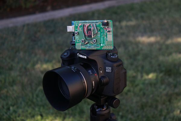 After adding in a display, a couple of buttons, and a more complex program, the self contained Arduino powered Time-Lapse Controller was born!
I have tried to make the instructions as clear and user-friendly as possible, but if any questions arise, feel free to ask!
Step 1: Parts
Parts:
– Arduino
– 7 Segment Display
– 220 Ohm Resistor x2
– 10K Ohm Resistor x2
– 470 Ohm Resistor
– Hookup wire
– NPN Transistor
– 3/32 Phono-jack
– hookup wire
– mounting surface (i.e. perfboard, breadboard, PCB)
Step 2: Wiring up the 7 Segment Display
Info:
After a bit of research, I found some sample code for a 7 segment display here. Taking a closer look at the first example, I noticed that each segment of the display need to be wired to a sequential pin on the Arduino. In the case of the example, pins 2-9 with pin 2 being the “dot” on the display.
Keep in mind that each display’s pinout is different and may differ from the display I used (from Radioshack), make sure to pay attention to its datasheet.
Instructions:
– Wire both GND pins of the display to GND on the Arduino with a 220 Ohm resistors
– Wire the display pins to sequential Arduino pins. In my case I used pins 3-9
– Wire the “dot” pin to the Arduino. For me, pin 2
Step 3: Wiring up the Buttons
Info:
Using this as a reference, I wired up the two buttons
Instructions:
Follow the pictures in the above link and the one enclosed and it should be pretty easy to figure out.
– using 10K Ohm resistors and hookup wire I connected the buttons to pins 11 and 12.
Step 4: Wiring up Shutter Control
Info:
After reading through rickadam’s instructable on time lapse, I based my circuit off of his design.
A DSLR camera uses a 2/32 phono-jack to interface with this circuit, but this could easily be adapted to just about any camera
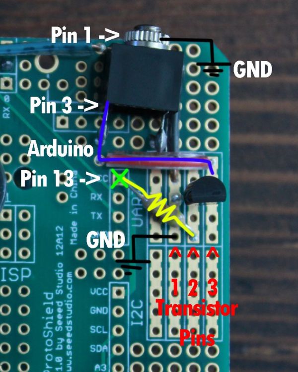
Instructions:
– Wire pin 1 of the phono-jack to Ardunio GND
– Wire the NPN transistor pin 1 to Arduino GND
– Wire 470 Ohm resistor from an open Arduino pin (in my case 13) to NPN transistor pin 2
– Wire pin 3 of phono-jack to pin 3 of the NPN transistor
(NOTE: the pin values given in this step are only used as identifiers and my not directly correspond with the values given on datasheets)
Step 5: Upload Blink and Create a Reference Sheet
Info:
My assumption is that the display I used and how it is wired up is different in comparison to your project. To make sure the final code runs properly, we need to change a few values within the program. To make that process easier, a reference sheet will be made.
Instructions:
– Open up Arduino’s Blink example and change the value of “led” to one of your segment pins. Download and run the sketch to the Arduino.
– Change the value of “led” again to another pin, download and run
– Continue this process while documenting the location on the display each pin lights up. Reference the picture as an example.
For more detail: Arduino Time-Lapse Controller