What this is:
This instructable will show you how to make your Arduino into an R/C interface that you can use for just about anything requiring remote control. I will also show you how I built an R/C lawnmower using my Arduino, a cheap R/C transmitter and receiver pair, and a couple of electric-wheelchair motors from Ebay. I have used this interface to control anything from basic LED’s to Bipolar stepper motors, mini-robots, lifeless R/C cars from the thrift store, and even a 100lb lawnmower (all with appropriate motor controllers). It is very flexible and easy to change and very simple to set up.
See a slightly different version of the Lawnbot400 in my new book “Arduino Robotics” , as well as a DIY Segway and several other bots.
Check it out in MAKE magazine in the April 2010 issue (#22) or here:
UPDATE 3-24-10
New wheel-barrow bucket mounted on top with hinges so it can dump its contents.
UPDATE 3-10-10: NEW CODE
And new video of the Lawnbot400 moving a bunch of dirt from my truck to the flower beds across the yard, also I updated the code again.
I added some new code to the project that is safer, including a manual kill-switch and a Failsafe switch.
To implement the Failsafe, I used another Atmega168 (or an Arduino), to control a normally-open 60amp power relay. The relay disconnects the power to the motor-controller unless receiving a “good” signal from the 2nd microcontroller. This signal is updated 2 times every second and is either ON or OFF. If the bot gets out of range, it loses power to the motors. If I flip the kill-switch on the Transmitter, it loses power to the motors. This is also a handy way to disable it remotely if anything were to go near it that wasn’t supposed to. The updated code for both microcontrollers is on the CODE page.
In addition to the failsafe, I changed the way the code reads the PPM signals to make it more reliable. Also, I realized that I was only able to run the bot at 80% speed with the old code, so now it is quite a bit faster and has more power (it can carry me across the yard @ 155lb).
Check out this new video of me riding the Lawnbot400, my wife driving it over a bunch of branches, then me making do some wheelies. Don’t worry, the mower was turned off this time since the grass didn’t need cutting, we were just having fun.
Disclaimer:
DANGER!!! This is a VERY dangerous piece of equipment if not handled appropriately. Since all the electronics have been home-built and the Arduino code is new, you MUST be very careful while operating anything heavy with this code. I have had 1 or 2 times during testing – and before adding a secondary failsafe – that the main Arduino jammed up and I temporarily lost control of the mower for a few seconds!!!! Though I have added several filters to discard unwanted signals and I rarely have any issues, an un-manned lawnmower IS STILL A POTENTIAL DEATH TRAP and I assume no responsibility for anything that happens as a result of your use of this code or this tutorial. This is meant as a guide for people who not only have the ability to build such a contraption, but the responsibiltity to operate it safely as well. Any suggestions or ideas on how to make this a safer project is always gladly accepted. Having said that, it’s also awesome.
Background:
Most R/C equipment comes packaged for a single specific use, which makes it easy to use but is very limited in what you can do with it. So using the Arduino as an interpreter between the R/C system and the motor driver, I can use any motor controller that I want (depending on the size of the motor and power required), reprogramming the Arduino to supply the required signals.
What I ended up with:
After successfully hacking a few R/C cars from the thrift store, I got bored driving them around the driveway and I was having a hard time convincing my wife that there was any usefulness in the revived toy car. So I decided it was time to make my biggest chore at home, a whole lot easier and actually put my Arduino to work, and thats how I ended up building an R/C lawnmower.
While designing the lawnmower, I thought it would be cool to learn about the electronics that made it move, so I designed and built my own motor speed controller (or H-bridge) to power the lawnmower. I looked around at every H-bridge design I could find before deciding to go with a Mosfet h-bridge that uses both N-channel and P-channel Mosfets.
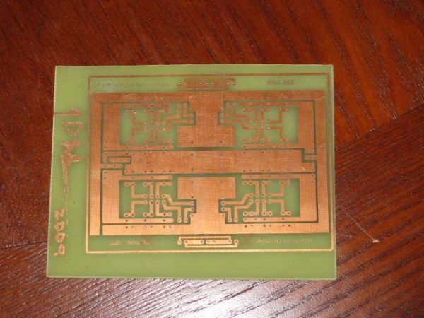
I built several different motor driver boards for this project, the first two were on Radio-Shack perf-board and the next 4 were designed using EagleCad and etched to a piece of copper-clad PCB, using the toner-transfer method. The most recent board is the one I use to mow the lawn as it has the ability to stay cool even while operating for long periods of time (30-40 mins straight) at 10-20amps and 24vdc. FWIW, I had to burn up a lot of Mosfets to find this out. If you want to see any of my other motor controllers, go to www.rediculouslygoodlooking.com and check out the Mosfet shield.
Here is what I bought already assembled:
FM R/C transmitter and receiver pair from ebay = $40
Arduino = $30
I already had a used push-mower = $60
Here is what I bought and assembled into the Lawnbot400 (as I call it):
(2) electric-wheelchair motors from ebay = $40 ea
(2) 12v marine deep cycle batteries – Walmart – $60 ea new (used batteries might work)
36″ pieces of 2″ angle-iron (2) and 1″ square-tubing (2) from Home Depot = $8 ea
36″ pieces of 1″ angle-iron (2) and 1″ flat steel bar (2) from Home Depot = $5 ea
(a lot) of nuts, bolts, washers, lock washers 3/8″ or 1/2″ with drill bit = $20
(2) caster wheels from Harbor Freight Tools = $14 ea
(2) drive wheels from Harbor Freight Tools = $8 ea
(36″) 5/8″ threaded rod with several 5/8″ nuts and washers from Home Depot = $8
(2) sprockets from Allelectronics = $5 ea
#25 roller chain and a few universal links from Allelectronics = $10 for 3′
sprockets from Electronics Goldmine = $1.50 ea
(24) mosfets from Digikey = $1 ea
(there were quite a few small parts for building the H-bridge, they are listed later on)
Step 1: Setting up
2. Upload code to Arduino (it is on the last page)
3. Make sure you are getting a good signalYou will need an R/C radio transmitter(Tx) and receiver(Rx) pair, which is the most expensive part of the project, but can be used for every future project you might have involving R/C. I went with a 6-channel FM system, but I have tested a 27mHz AM transmitter/receiver and it works just as well. The beauty of the Arduino is that if you want to adjust the deadband or the motor-speed at turn-on, (unlike commercial ESC’s) it is all easy changed in the Arduino IDE.Once you have your radio, all you need to do is upload the code to your Arduino, plug in the 2 channels that you want to use from your radio receiver into Digital pins 2 and 3 of the Arduino (these are the 2 external interrupt pins on the Arduino) and you are ready to control whatever you want. If you don’t have a batter pack for the receiver, you can run jumper wires from the Arduino +5v and GND to the R/C receiever for power, you only need to supply a single channel with GND and +5v (it is not necessary to power every channel).
Upload the code using the Aruino IDE (I am using version 0016 on Ubuntu).
I started by controlling 3 LED’s with 1 channel on a breadboard. I wired a red LED to be Forward (digital pin 9), a yellow LED for Reverse(digital pin 5), and a green LED for Neutral (digital pin 12). This allows you to adjust the code to fit the needs of your radio system. You will have smooth 0-100% PWM control of both LED’s and the neutral light will turn on when the control stick is centered. If needed, you can widen the deadband for Neutral, but doing so will increase the speed at turn-on (which starts at 0%, so that would likely be desirable). See pictures.
—————————————-
The code has 4 PWM outputs for motor control:
channel 1 Forward = Arduino digital pin 9
channel 1 Reverse = Arduino digital pin 5
channel 2 Forward = Arduino digital pin 10
channel 2 Reverse = Arduino digital pin 6
2 outputs for Neutral indicator lights:
channel 1 = digital pin 12
channel 2 = digital pin 13
The 2 INPUTS from the R/C receiver should go to:
channel 1 = digital pin 2
channel 2 = digital pin 3
—————————————
If you are interested to see your readings, turn on your Serial Monitor in the Arduino IDE (set to 9600bps) and you can see the actual real-time pulse readings for each channel, they should read:
full forward = 2000 (2 milliseconds)
center = 1500 (1.5 ms)
full reverse = 1000 (1 ms)
These readings reflect the number of microseconds that the pulse signal from the R/C receiver stays HIGH (or at 5v). The typical Servo signal that comes from an R/C receiver is a pulse whose length varies from approximately 1 ms to 2 ms with 1.5 ms being Neutral (which should also be the position that the control stick returns to when you let it go). The transmitter reads the position of the control stick and sends that pulse length about once every 20milliseconds. So it is constantly updating for precise control (for more info, look up PPM on wikipedia). If you push the transmitter control stick forward, the reading should go up to 2000, if you push it backward it should go down to 1000. You can also use a voltage meter at this point to see that Digital Pins 5, 6, 9, & 10 will be changing from 0-5v depending on the position of the control sticks on the R/C transmitter.
If you care to know, the code uses the Arduino’s 2 external interrupts to capture when the Rx signal pin changes states (goes from HIGH to LOW or vice versa), when it does at the beginning of each signal, it calls the interrupt function which reads the digital state of the pin and if HIGH, it records the microseconds value on the Arduino system timer0. It then returns to the loop until the pin goes LOW, at which point it subtracts the previously recorded microsecond value from the new current microsecond value to determine how long the pulse stayed HIGH (which tells us the position of the Transmitter control stick). It then does that over and over really fast.
I have the values constrained from 600-2400 in the Arduino code to keep things simple. Once it receives the signal and constrains it, it maps that value to be proportionally between 0 and 511, where 255 will be Neutral. The code then determines when the value changes and uses a function to determine the appropriate 0-255 PWM value in the appropriate direction and each direction has it’s own PWM output pin to control the H-bridge.
On a side note:
To make things easier, I built an Arduino-based breakout board using Radio-Shack perf-board, a 28pin DIP socket, a 16mhz oscillator, and a bit of wire. I also added a set of female-headers in such a way that I can plug my R/C receiver directly onto the breakout board. For secure connections while mowing grass, I added screw-terminals on each Output pin and each of the 6 channels from the receiver. It also has a built in 5v regulator to power both the Atmega168 from the Arduino and the R/C receiver (which gets power when you plug it onto the breakout board). So you just route jumper wires from the channels you want to use on the receiver, to the Atmega digital pins 2 and 3. I also added 2 LED lights that are hard wired to the digital pins 12 and 13 for the Neutral lights for each channel so I can easily see when I am in neutral.
Since this bot is a Tank steer setup with 1 drive motor on each wheel, the coding is very straightforward where the left stick controls the left motor and the right stick controls the right motor. Both sticks forward means lawnmower goes straight forward, both backward and it goes in reverse. If you push the left forward and the right backward, it does a zero-turn circle. As you can imagine, mowing the grass is really fun now.
Step 2: The Motor Driver
The design is simple: 2 P-channel mosfets control the high-side switches and 2 N-channel mosfets for the low-side switches. But instead of using 1 mosfet for each switch, lets use 3. Now we have 12 mosfets per H-bridge (3 mosfets x 4 switches) and theoretically the ability to carry 150 amps (that is not accurate though). The board is as small as I could make it with nothing touching. Each set of 3 mosfets have heatsinks and are bolted together to help dissipate heat. Also, there is an 80mm cooling fan mounted directly above mosfets to further keep them cool. The mosfets are very good at handling sudden changes in direction and speed changes.
Since there are 24 mosfets in total (8 groups of 3) I dubbed it the Triple-8. It is running at the Arduino default PWM frequency of 1kHz (I plan on playing with that to get the frequency higher). The board has 4 inputs, 2 for each bridge. If you bring an input HIGH, that side of the bridge goes HIGH.
Ideally, you would control the board by holding 1 input LOW and applying a PWM signal to the other input. This allows for easy speed control. I have written into the code that if you bring digital pin 7 HIGH, the code switches to Relay mode and either turns the mosfets all the way ON or all the way OFF. This is far more difficult to control, but is useful sometimes.
If you are interested in building your own H-bridge you can download the eagle file to etch a pcb and the schematic to show where everything goes. You can get everything to make this dual h-bridge at Radio-shack (including the copper clad), except the Mosfets and a special resistor network I used to save space. I bought most of the parts from Digikey though because it was cheaper and arrives to my house in 2 days.
Here are the parts needed for this motor driver:
(12) FQP47P06 – P-channel mosfet 47a 60v – Digikey – $1.73 ea
(12) FQP50N06L – Logic level N-channel mosfet 52a 60v – Digikey – $1.04 ea
(4) 2n7000 – Logic level N-channel mosfet 200ma 60v – Digikey – $0.26 ea
(8) 4606X-1-470LF-ND – 47ohm bussed resistor network – Digikey – $0.25 ea
(6) ED1609-ND – 2 position screw terminal – Digikey or Radio Shack- $0.46 ea
(24) CF1/84.7KJRCT-ND – 4.7k 1/8w resistor – Digikey or Radio Shack – $1.78 (for 50pk)
(1) PC9-ND – 3″x4.5″ 1-sided copper-clad .064″ 2oz copper – Digikey or Radio Shack- $4.66
(4) P5575-ND – 1000uf Capacitor or similar – Digikey – $1.19 ea
(1) 330ohm – 1kohm resistor 1/4w – for power LED, doesn’t have to be exact
(1) power LED any color you like, I use the 3mm size to save space
Maybe something smaller?
If you are going to use this for something smaller than a 100lb lawnmower, you can look up one of the many H-bridge circuits and build your own smaller motor controller with as few as 4 mosfets (or BJT transistors) or even use a packaged IC H-bridge like the l293d (dual 1 amp) or the l298n (dual 2 amp).
Or if anyone is interested, I will post a schematic and Eagle .brd file for a smaller version of this H-bridge that only requires 8 mosfets total (everything else is the same), and it can handle about 10amps at 24vdc.
Etching:
I am not going to go into all the details of PCB etching, because there are already many excellent instructables on that topic. So once you download my .BRD file of my motor controller, all you need to do is print the .brd file onto some magazine paper using a laser printer, and iron that onto a piece of clean copper-clad. Then etch it with your favorite etchant solution (I use 2 parts Hydrogen Peroxide to 1 part Muriatic Acid and it works perfectly). And remove the toner with Acetone when done etching.
For ease of assembly I designed this board to be Single-sided and to use only through-hole components, no surface-mount stuff to mess with! Yay for you.
You can get the .brd files for the various h-bridges at www.rediculouslygoodlooking.com
Step 3: The Wheels
If you are smart and have more money, you can find a set of wheelchair motors that have the wheels mounted to them.The CHEAP way:
I could not find any in my price range, so I went with just the motors, then bought wheels, then sprockets. Believing it would not be strong enough to mount the wheels directly to the motors, I opted to mount the drive wheels on an axle, then the motors to the frame, and use chain to transmit the power. A picture is worth 1000 words, so look at them carefully.
Mount the sprockets to the wheels:
I had to place the sprocket on the center of the wheel and drill 3 holes through the sprocket and then through the wheel itself. Once the sprocket is lined up and properly centered, I placed the 3 bolts through the sprocket and wheel and tightened them up as much as possible. I then welded the sprocket to the wheel hub to keep it centered.
The wheels from Harbor Freight Tools have built in bearings for a 5/8″ shaft, hence the 5/8″ threaded-rod we are going to use as an axle.
Repeat this process for both wheels.
There is more detailed info tagged in the pictures.
Step 4: The Frame part A
measuring tape
angle-grinder
ratchet set
crescent-wrench
a level
electric drill
bolts, nuts, washers, and lock washers of either 3/8″ or 1/2″ diameter and 3/4″- 2″ long
drill bits the size of the bolts you are using
1″ and 2″ angle-iron (36″ long pieces) you’ll need both
1″ square tubing (36″ pieces, steel)
1″ flat steel bar (36″ long pieces)
the 4 wheels you got from Harbor Freight Tools (2 drive wheels and 2 caster wheels)
5/8″ threaded rod (36″ long) and several 5/8″ nuts/washers
First you need to plan out the frame of your bot. Since I was attaching a lawnmower, I started by measuring the height that the lawnmower stood off the ground and took some basic measurements to see how big the frame needed to be. My frame turned out to be about 24″ wide (this distance must match the width from the center of the rear lawnmower wheels) and 48″ long (long enough for the front caster wheels to swing 360 degrees without hitting the front of the mower deck) and about 18″ tall. Since we want the height of the mower-deck to be adjustable, we are going to attach the mower to the frame by removing the lawnmower wheels and using angle-iron to suspend the mower-deck from the frame of the bot.
1. I started out by using 2 of the 36″ pieces of angle-iron (2″ wide) for the main part of the frame running long-ways.
2. Cut the rear-piece of angle-iron the width of the rear of the mower (this measurement will be from the center of the left-rear wheel to the center of the right-rear wheel).
3. Drill holes in the ends of the angle-iron and bolt the rear-piece to the adjacent pieces from step 1, making sure they are straight.
4. Cut two front-pieces using 1″ square steel tubing, the same length as the rear. We need 2 in the front to bolt the caster wheels to.
5. Drill holes and bolt these 2 pieces to the front of the angle-iron from step 1. You have to measure the holes from the 2 front caster wheel’s mounting plates and drill the pattern into the front square tubing bars. Then bolt the wheels through those holes onto the front of the frame.
I later added another set of 2″ angle-iron bars to the front caster wheel assembly to make the length of the bot adjustable at the front (see pics)
Now we should have a rectangular frame with the front wheels attached.
Step 5: The Frame part B
7. Now drill (2) 5/8″ holes, 1 at the bottom of each frame riser (about 1″ from the bottom), this is where the drive axle will go through.
8. Drill 2 holes at the top and bolt the frame risers to the rear of the main-rectangular frame with the frame-risers pointed down.
9. Now feed the threaded-rod through the bottom holes of the frame risers and use 4 nuts to secure the frame risers to the drive axle (1 nut on each side of each frame riser, tightened down).
10. put the rear wheels on the axle and use 1 more nut on each wheel to secure them to the axle (these wheels have built in bearings). The sprockets should face inward toward the frame.
Now we should have a frame that stands on it’s own with 4 wheels. However, the rear axle is not completely secure yet. We will need to add 2 braces from the bottom of the frame risers (near the axle) to the main part of the frame in order to keep the frame risers positioned properly. These braces can be flat steel and do not need to be very thick, they are just keeping the frame risers from moving.
Measure about 2″ above each axle and drill a hole, then measure how far down that hole is from the top-rear of the frame and measure the same distance from the rear of the frame toward the front. Drill another hole on each side at this measurement. The support braces will need to be measured to be bolted in through these holes on each side (see pictures). The placement of the support braces is less important, meaning you can bolt them in wherever is convenient, as long as they are present.
Step 6: Mounting the motors
Cut an 8-10″ section of 2″ angle-iron, depending on how much room your motors need to mount. Mine only needed about 4″, so I made it 8″ to have plenty of room for the mounting bolts. Drill a hole about 1.5″ from each end of the top of this bar, this is where the mounting bolts will go through the frame.
Mount the motor to the motor mounting plate:
Now you have to find the center of your motor mount plate (the 8″ long piece of 2″ angle iron) and measure the mounting holes on your DC motors. Use a sharpie marker to plot the hole pattern from the motor, centered onto the motor mount plate. My motors have (4) 1/4″ diameter tapped holes in a rectangular pattern on the bottom of the gear box.
Drilling and cutting the adjustment holes on the frame:

Cutting and connecting the chain:
Now get your 10′ of #25 chain and wrap it around the main drive sprocket on the wheel. With the motors pushed all the way toward the back of the frame (closest to the drive wheel sprockets), wrap the chain around the motor drive sprocket and mark where they overlap. You need 2 of the universal chain links from to connect the 2 loose ends. Cut the 2 pieces of chain and connect them to each side with the universal links to connect them.
Tensioning the chain:
Push the motor mounts forward until there is good tension with the chain, and tighten up the bolts that hold the motor mount plates to the main frame.
Now you can generate electricity. Connect a voltage meter to 1 set of motor terminals and push the bot around.
For more detail: Arduino R/C Lawnmower (painted)