Summary of Arduino Project 8: Stompy the robot (part 1)
This article details "Stompy," a low-cost, four-legged walking robot built using an Arduino Uno and the Dagu Quadbot chassis. The project solves power management challenges by utilizing a DC-to-DC converter to regulate voltage from NiMH batteries, preventing Arduino resets under heavy servo loads without requiring multiple battery packs. It features an ultrasonic sensor for obstacle avoidance and uses a specialized sensor shield to manage motor connections efficiently.
Parts used in the Stompy Robot:
- Arduino Uno R3
- Arduino Sensor Shield V5.0
- Dagu Quadbot chassis kit
- DC-to-DC converter
- SPST toggle switch
- HC-SR04 sensor
- TowerPro SG90 servo motor
- 470uF/16VW electro capacitor
Our first Arduino robot called Rolly in our February issue proved to be a popular project. Powered by an Arduino Uno board it was easy to put together and cost very little. In this project we upped the ante again with our first walking robot appropriately called Stompy. He’s a quadruped a four-legged walker and he’s physically about as simple as you can make a walking robot.
If you look online there are plenty of six- and even eight-legged robots but the one thing they all have in common is that they usually cost a small fortune – upwards of $300 and typically closer to $500. We’ve found a much lower-cost alternative called the Dagu Quadbot designed by Australian Russell Cameron available from RobotGear for $55 including shipping. For that price you get the main plastic chassis the leg pieces and eight tiny plastic-gear servo motors; the rest including the electronics that drive it is up to you.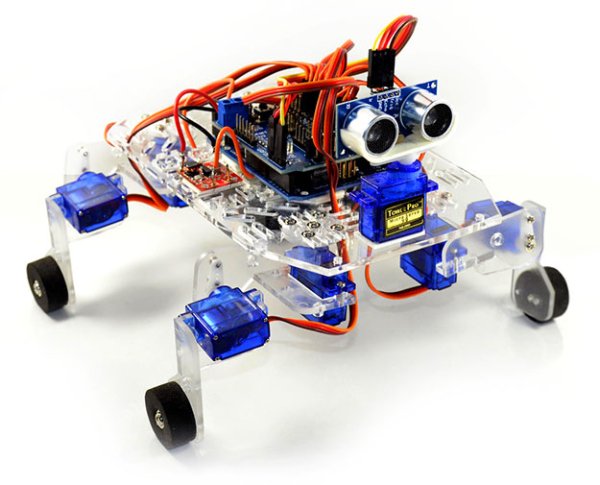 Plastic-gear motors mean you won’t be tackling Mt. Everest with this little guy although he should be enough to pique your interest and save you a fortune buying something else.
Parts list |
||
| Part | Cost | Source |
| Arduino Uno R3 | $13.20 | eBay |
| Arduino Sensor Shield V5.0 | $4.86 | eBay |
| Dagu Quadbot chassis kit | $55 | eBay |
| DC-to-DC converter | $3.14 | eBay |
| SPST toggle switch | $1.95 | eBay |
| HC-SR04 sensor | $1.88 | eBay |
| TowerPro SG90 servo motor | $2.37 | eBay |
| 470uF/16VW electro capacitor | $0.75 | Jaycar |
| TOTAL COST | $83.15 | |
Our design
Normally servo motor-based robots require a specialised controller board designed for the purpose and there are a few around. You can also use a standard Arduino Uno board although because Arduino and servo motors have different voltage requirements you typically see Arduino-based bots with two batteries: the standard four AA cells for the servo motors and a 9V battery for the Arduino board itself. However we’ve come up with a unique design that sticks with an ordinary Arduino Uno board and only needs the basic four AA-cell battery.
The basic problem we’ve overcome is that the Arduino’s ATMEGA328P chip needs 5VDC power but you need to feed it at least 7VDC to allow the onboard voltage regulator enough head room to generate the clean 5VDC needed. That’s a problem because the lightweight servo motors in this kit will blow up if they’re fed with 7VDC. What’s more the Arduino’s regulator can’t drive the servo motors directly.
Arduino Sensor Shield V5.0
We’re introducing another Arduino expansion board this month called the Arduino Sensor Shield. It’s a low-cost (under $8 shipped) board that allows you to connect a range of sensors to your Arduino using easy-to-attach jumper cables. It’s a simple board with no electronics on it other than a couple of resistors and an LED. Its main role is to supply those header pins to make it easier to attach external devices like our servo motors.
Heavy load
Stompy requires nine servo motors all up: two for each leg and one for the neck; however the electrical demands of powering those motors puts a heavy load on the power supply. Given we’re using four AA Nickel Metal Hydride (NiMH) rechargeable cells we have plenty of power yet not much voltage – around 5.5VDC at best under no load. As soon as we ask the battery to handle those motors its voltage begins to sag to below 4.5V. As soon as that happens the Arduino Uno drops below its operating voltage and resets itself. This results in Stompy starting and stopping starting and stopping as the battery voltage yo-yos up and down.
The quick and dirty solution is to use two batteries: four NiMH cells to deliver 4.8-5.2VDC for the motors and a small single-use PP3/9V battery to power the Arduino. Personally we hate that solution – it’s just dodgy. You’ve now got two power sources to check and you’re using a battery that was designed for transistor radios in the 1950s not driving microcontrollers. What we need is a solution that fixes the voltage reset issue without needing that PP3 battery.
DC-to-DC converter
The solution is a tiny little circuit board the size of a postage stamp. It costs around $3 including shipping on eBay and solves the problem perfectly. It’s called a DC-to-DC converter. They’re normally sold inside cases to act as emergency USB power for charging phones or on their own with a USB Type A socket on the end although you can buy the circuit board separately and use it to deliver 5VDC at up to 1000mA from as little as 2.5VDC input.
How it works will take more space than we’ve got but here’s the abridged version. It uses a charge pump that switches a small inductor on and off at a high 1MHz frequency. Inductors are weird components that try to maintain their electrical field when the current is switched off by raising their voltage. The voltage is dumped into a capacitor through a fast-recovery blocking diode and regulated by the switching circuitry to a very steady 5VDC.
So instead of powering the Arduino Uno directly from the battery we solder a connecting wire from the DC-to-DC converter’s output directly to the 5VDC pin of the Arduino and bypass the onboard regulator. While the battery voltage varies significantly under the load of the motors the converter provides a regulated 5VDC output that keeps the Arduino happy. Most importantly the whole thing is powered by just one battery.
However there’s one other issue: the servo motors are driven by the sensor shield and the shield is connected directly to the battery. The shield is also connected to the Arduino with our DC converter voltage. In order for all of this to work we need to separate the voltage rail of the shield from the Arduino as the DC converter creates a new 5VDC voltage rail we have to respect.
The solution is supplied by the sensor shield. Right near the battery input terminal block there’s a PC board jumper. Remove it and the 5V supply rails are now separated and everything works. Make sure your sensor shield has this jumper otherwise the robot won’t run. Finally we only need three wires to the converter: DC voltage in the 5VDC output and the common ground (0V) line that goes to the battery ground and the Arduino’s ground plane. The fact that it’s a common ground means we only need one ground connection to the DC converter. Apart from wiring up the power switch connected to the battery the only soldering you need is the three wires to the converter.
Turning heads
We’ve borrowed the same basic eyes and neck from our first robot Rolly and used them here to give Stompy some corrective feedback. The HC-SR04 ultrasonic sensor sends out 40kHz bursts and measures the time for the echo to return to give us an accurate distance in front. By putting the sensor on top of another servo motor we can rotate the sensor and scan the surroundings without having to move the whole robot in that direction.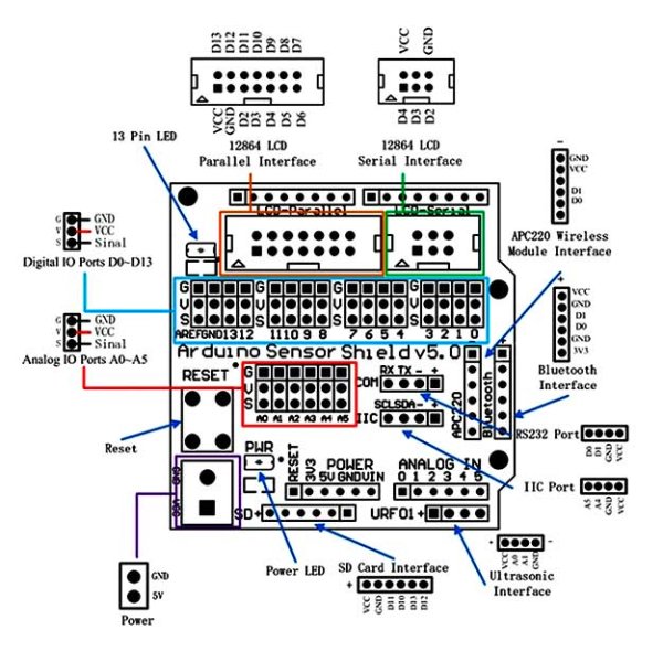
Power
Finally to keep things compact we’ve used a basic four-cell battery holder stuck to the underside of the Perspex base and included a single-pole single-throw (SPST) switch to quickly control power.
Use NiMH rechargeables
Single-use AA batteries are convenient but a waste. They’re also Stompy’s Kryptonite. Standard AA batteries deliver around 1.6VDC voltage with no load. Add four together and you’re looking at 6.4VDC which is too much for our DC-to-DC converter. With an input voltage that high the output becomes the input minus the blocking diode voltage drop (0.6V) which can be as much as 5.8VDC. Connect that directly to the Arduino and it’ll blow up. At best NiMH cells deliver 1.4VDC or 5.6VDC in a four-cell block. Take away that 0.6V diode drop in the DC converter and the highest voltage output you’ll get is 5V flat. As the voltage drops the DC converter kicks in and ensures the output stays at 5VDC and the whole thing runs happily. So just remember NiMH cells only.
For more detail: Arduino Project 8: Stompy the robot (part 1)
- What is the total cost of building the Stompy robot?
The total cost listed for all parts is $83.15. - Can I use standard single-use AA batteries for this project?
No, standard AA batteries deliver too much voltage which can blow up the Arduino via the DC-to-DC converter. - How many servo motors does Stompy require?
Stompy requires nine servo motors in total: two for each leg and one for the neck. - Why was a DC-to-DC converter necessary for the design?
It regulates the voltage from the battery to a steady 5VDC to prevent the Arduino from resetting when the battery voltage sags under load. - What type of batteries should be used to power the robot?
You must use NiMH rechargeable cells because they provide the correct voltage range for the DC-to-DC converter. - Does the Arduino Sensor Shield have electronics on it?
No, it is a simple board with no electronics other than a couple of resistors and an LED. - What component is used to scan the surroundings for obstacles?
An HC-SR04 ultrasonic sensor mounted on a servo motor is used to send out bursts and measure distance. - How do you separate the voltage rails on the sensor shield?
You must remove the PC board jumper located near the battery input terminal block to separate the 5V supply rails.