For a while I have been looking for a way of getting a reading of main and leisure battery voltage, and inside and outside temperature in the van. I spent ages on researching and found some bits here and there that might help, but nothing to do the whoe job, and nothing really satisfactory, until finally I found a link to the Arduino website. Never having heard of it before, I did a bit of reading and it seemed perfect. So I set about designing and building the necessary circuitry … below is a brief summary of what I came up with. Before I go on I should tip my hat in this direction – seems like tobes49 thought of it first: http://www.vwt4forum.co.uk/showthread.php?t=198976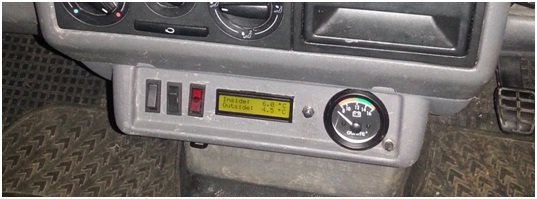
First, the Arduino is a small board that allows monitoring of sensor inputs on one of many analogue or digital channels. Its really simple, you just write a short bit of code to tell it what to monitor, upload it to the chip, and away you go. Find more details at www.arduino.cc. There are several versions; I based my project on the Uno R3. As for sensors, you can sense just about anything for pennies. Have a look at www.proto-pic.com or www.oomlout.com for example. I did think about using the Raspberry Pi for this project, but once I found the Arduino I realised the RPi is massively OTT.
I’m going to jump straight to the end result – I’m sure you aren’t interested in the two months of development, debugging, pulling my hair out trying to get it to work. The final circuit has the following functionality:
• 2 temperature sensors, one mounted inside the van, the other behind the front bumper
• Measures the voltages of the two batteries
• Monitors a three-axis accelerometer mounted in the van, from which it calculates pitch and roll angle;
• Monitors the state of a button, used to display either main/aux battery volts, inside/outside temp, or pitch/roll angle
• Displays warning if either battery or temperature is out of set range
To implement the circuit, I bought some copper board from Maplin, and worked out how to wire the above circuit up so that I could attach it directly to the Arduino. Here is a photo of the completed circuit mounted on the Arduino (which is underneath so you cant see it).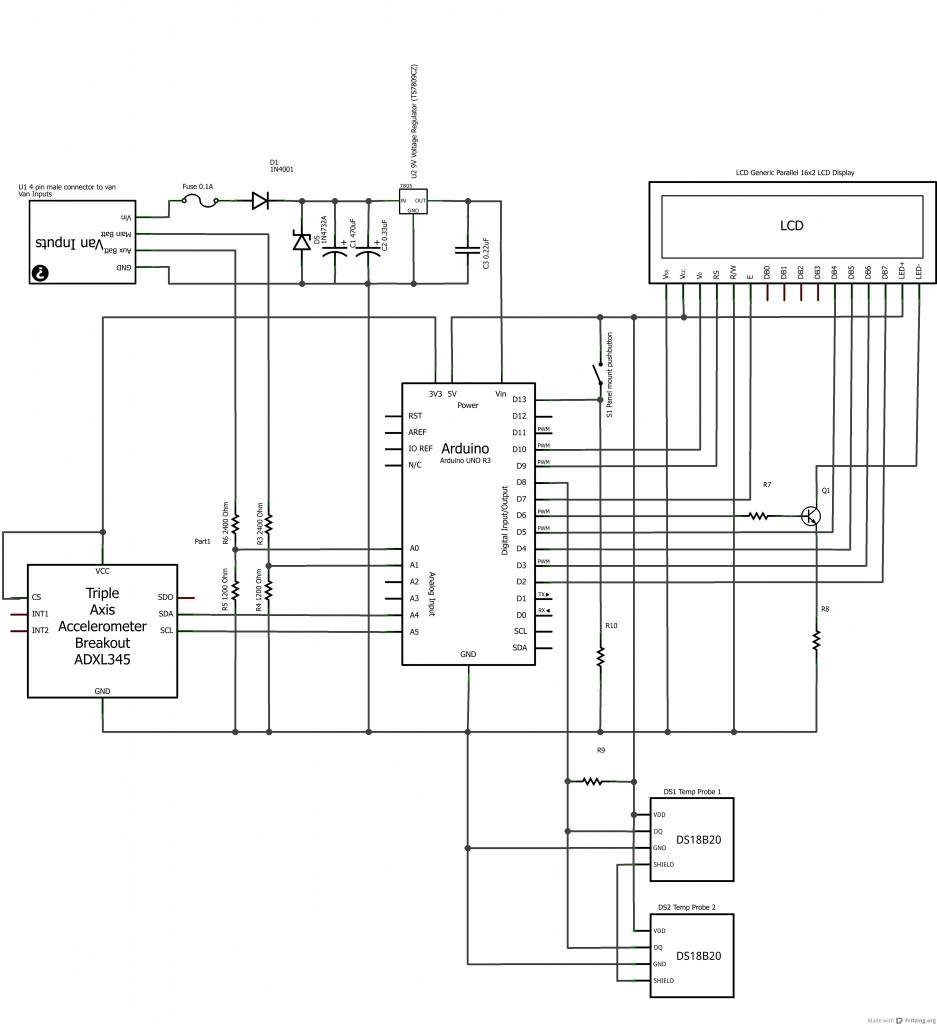
Then I simply mounted the LCD screen as shown in the picture below (the other switches on the panel are inside lights, and the DURITE was my first attempt at volt gauge, but analogue gauge is utterly useless); you can also see to the right of the screen the pushbutton that controls which screen is displayed. All in all I am very pleased with the result – the Arduino is awsome and massively expandable. I have more ideas about incorporating rear parking sensors, security alarm etc, but with a baby coming soon I’ve had to cap my ambitions for the timebeing. Anyway, thought I would share, I hope someone finds it useful.
For more detail: Arduino powered voltmeter and temp gauge