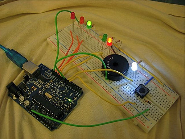
Summary of Arduino: Making a set of traffic lights
This article guides users in building a controllable and configurable traffic light system using an Arduino, suitable for beginners. It covers component layout, LED polarity, breadboard wiring, and basic electronics concepts like digital and analog inputs. The project emphasizes safety by warning against powering the circuit before all components are correctly placed. Readers can later expand the project to include cross-traffic logic, EEPROM programming, or multi-Arduino communication.
Parts used in the Arduino Traffic Lights Project:
- 1x Breadboard (34-0655)
- 1x Jumper Links (34-0495)
- 2x Red LEDs (55-0155)
- 1x Orange LED (55-0124)
- 2x Green LEDs (55-0120)
- 1x White LED (55-1640)
- 1x Piezo Sounder (35-0282)
- 1x Push to make button (78-0630)
- 1x 10K Resistors (62-0394)
- 1x 220ohm Resistors (62-0354)
- 1x Arduino Diecimila
- Optional 1x 3m USB Cable (19-8662)
 Arduino – Getting started guideThis document will explain in simple terms about the basic electronic components we will be using and how to use them, it also describes digital, analogue and serial inputs and outputs and how they are used.You may have read my previous tutorial on traffic lights, this will be a similar concept however will be easier to build and more feature rich, because of the simplicity of the Arduino development environment.After this project, you might like to extend it by…
+ Making the lights work for cross roads (expanding the complexity of the sequence).
+ Making the settings programmable by using the EEPROM and Serial port.
+ Making the lights communicate with another Arduino running the same code.
Step 2: Getting started
Step 3: LEDs
Before we begin ensure all LEDs are connected the right way around. The short lead goes on the right and the longer on the left.
We will be adding the resistors later so be sure not to plug in any power yet as it could damage the LEDs
The image below shows the long and short leads, and then the second image shows how they should be wired, third showing the order.
TIP! Ensure that yu have the LEDs spread across from the 5 column bit to the two column bit or else they will not work and you will have a short circuit.
Step 4: Piezo
We will be coming back to this and will need to lift it to install jumpers to the Arduino but for now just put it in place with one pin on either side of the central divide so we don’t short between the two pins.
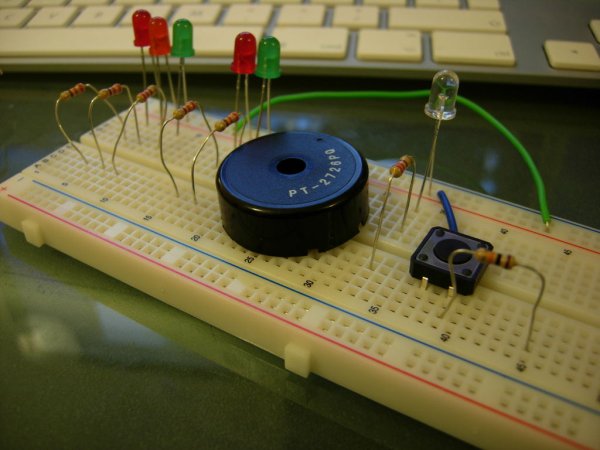
The bread board pins are connected from left to right in two sections of 5 with a divide in the middle to separate the two sections, and the 2 outer pins are connected from top to bottom in two columns, these are on both sides but are not connected from one side of the board to the other, in other terms these can be used to provide two separate circuits independent of each other if required.
Additionally on some boards the top and bottom halves are not connected so you may have to make the jump using a wire from the top half to the bottom half if your circuit does not work.
Parts
You will need a few parts, if you already did my previous project on AVR microprocessors, then you don’t need to buy the same things again, You should only need the Arduino and USB lead which you can get from Tinker.it and some form of 5v piezo sounder.
These are minimum requirements you could order more for backup or expansion of this project.
1x Breadboard (34-0655)
1x Jumper Links (34-0495)
2x Red LEDs (55-0155)
1x Orange (not amber) LED (55-0124)
2x Green LEDs (55-0120)
1x White LED (55-1640)
1x Piezo Sounder (35-0282)
1x Push to make button (78-0630)
1x 10K Resistors (62-0394)
1x 220ohm Resistors (62-0354)
OPTIONAL – 1x 3m USB Cable (19-8662)
Rapid Online – £20.70
1x Arduino Diecimila
Tinker.it- £20.35
The total was £41.05 which is higher than the AVR tutorial but its worth it and that includes delivery.
The delivery charges are quite high at rapid so why not shop about while your there and at Tinker.it and see if you can find some parts which you can play with at a later date. More LEDs and other bits which you think you can play with.
Good news is you won’t need any tools or soldering for this project, its just pushing bits together! Once you have all the parts you are ready to assemble your project, however if you are planning to make this project more permanent you will want to get some form of strip board to solder your work down once its working.
For more detail: Arduino: Making a set of traffic lights
- What is the main goal of this tutorial?
The tutorial aims to create a set of controllable and configurable traffic lights while teaching the basics of Arduino. - How should the LED leads be connected on the breadboard?
The short lead goes on the right and the longer lead goes on the left. - Can I power the circuit before connecting all components?
No, you must not plug in any power yet as it could damage the LEDs before resistors are added. - Does this project require soldering tools?
No, you do not need any tools or soldering for this project as it involves just pushing bits together. - How can I extend this project after completion?
You can expand it by making lights work for cross roads, programming settings via EEPROM, or enabling communication between two Arduinos. - What is the recommended position for the Arduino relative to the breadboard?
It is best to have the Arduino to the left of the breadboard and disconnected initially. - Are there specific resistor values required for this build?
Yes, the project requires one 10K Resistor and one 220ohm Resistor. - Why might the top and bottom halves of a breadboard not work together?
On some boards the top and bottom halves are not connected internally, requiring a wire jumper to link them. - What happens if LEDs are not spread across the correct columns?
If they are not spread from the 5 column bit to the two column bit, they will not work and may cause a short circuit. - Is it possible to make the project permanent later?
Yes, if planning to make the project permanent, you should get a strip board to solder your work down once it works.