My first meeting with microcontrollers was a few decades ago (you might remember the first Parallax Basic Stamps) but with the Arduino platform it happened more recently, only 6 years ago and although at that time the development boards were quite difficult to find, even then I found it was a very interesting thing. Later I bought a so-called ‘electronic kit’ with an original Arduino Uno, with LEDs, buttons, some sensors, relay, motor, infrared receiver and many other useful things 🙂 My first installation was a button connected to the Arduino which lit one LED.
Now everything has changed, Arduino has become very cheap, you can find a lot of copies on the Chinese market, the platform allows the connection of hundreds of kinds of sensors, hundreds of kinds of peripherals and with the help of libraries writing programs has become fast and easy. I have advanced quite a lot since the first installation (button plus led) and I would like to present to you in this article one of my last attempts. In this application the main role will belong to the reed switch. The simplest application of this magnetic sensor is like my first Arduino installment, the status of the reed switch is read by a digital input of an Arduino nano and a led (in this case the onboard led) lights up when we bring a magnet closer to the reed switch.
It is beautiful but not very useful, in general we want to do much more than we can do with this simple assembly. So in the following lines of my article I will present a couple of projects based on this application.
However a little theory first about the reed switches…
Step 1: The Reed Switch
The reed switch can be considered as the simplest magnetic sensor. It consists of a pair of flexible, ferromagnetic blades, as contacts of the switch, hermetically encapsulated in a glass tube filled with inert gas. These blades are attracted to each other when a magnetic field approaches closing the contact.The difference between the value of the magnetic field over which the contact is closed and the value of the field under which the contact is opened being large (hysteresis), the device is well immunized against magnetic field fluctuations.
The reed switches do not need maintenance and are very well protected against dirt and dust. The contacts have a long life. They can switch currents from 0.1-0.2 A to 100-200V. Reed switches are mainly available with normally open contact or normally closed contact. Reed switches can be used in many applications due to their simplicity of construction, low price, operational safety and non-existent power consumption. For example, they are used in security systems to monitor the opening of doors and windows. A permanent magnet is attached to the moving side, and a reed switch is mounted on the fixed side as a proximity sensor. The contacts close when the magnet is close enough (doors, windows closed) and open when the magnet is removed (doors, windows open). They can also be used to detect the level of liquids or in the automotive industry, etc Due to their construction it is very interesting to see how the magnetic field acts on them. For a reed switch to be actuated, a magnet must be close to it at a certain distance. This distance depends on the magnetic sensitivity of the reed switch and the power and size of the magnet. When the magnet is close enough, the Normal Open contacts will close. When the magnet is removed, the contacts will open. The closing distance is always less than the contact release distance.
There are several ways in which a reed switch is operated with a magnet and some examples of magnet movement are shown below. But unlike what is presented in the literature, in my project I used some balls as magnets so the results are not really standard.
Rotating the magnet or reed switch, normally on their axes, reverses the magnetic polarity, resulting in two closures per one rotation. When the axes are parallel, the switch closes. When the axes are perpendicular, the switch opens. Although the poles are reversed, they still induce opposite poles that close the switch. More about this:
These operating modes apply only to a certain extent in my case, using magnetic balls the movements are compound and cannot be accurately predicted when the contacts are closed or opened.
After this brief introduction, let’s return to the project. My idea was to do more with the simple installation from the intro so I thought about what it would be like to have more reed switches that each operate its own LED. For this I made a matrix of reed switches and a matrix of LEDs, where the LEDs matrix is mounted above the reed switches matrix.
Note
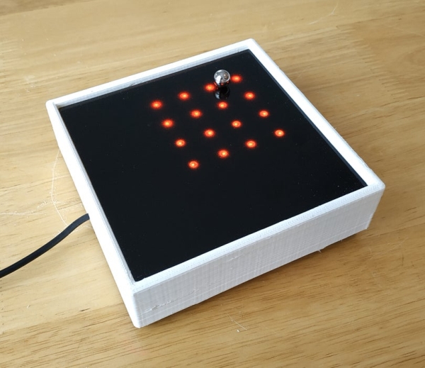
As I said above, using magnetic balls instead of magnetic bars, the action of reed contacts is much more complicated, practically unpredictable due to the rotation of the balls. But this really gives an extra charm: you never know what will happen, how the reed contact will behave when the magnetic ball approaches it. Also, the literature does not mention an interesting thing: not only the magnet attracts the contacts but also the contacts attract the balls (action – reaction) and it is interesting how the balls sometimes get stuck above a reed contact and an extra force is needed to further move the balls. In essence, this is how the arduino magnetic board was born 🙂
Step 2: The Reed Switch Matrix

Materials, components required:
- Reed switches 36 pcs;
- Relay support and template for bending the legs of the reed contact – files on Tinkercad;
- Wires, Self-adhesiv paper tape.
For the construction of the matrix of reed switches I used 36 switches like the ones in the picture. I printed the support on the 3D printer and I also printed a simple template with which I can bend the legs of the reed contacts so that the magnet acting on the contacts from above is parallel to the movement of the reed contact contacts,
Also the bending of the legs must be done carefully because the glass balloon of the reed contact can break easily so it must be made with a little attention. The template helps in this as well. I then made the connections according to the scheme above. Between the connections you notice that I glued some self-adhesive paper to insulate the connections between the lines and columns.
In order to visualize which of the reed switches are making contac, I also made an array with RGB LEDs…
Step 4: The Arduino
Materials, components required:
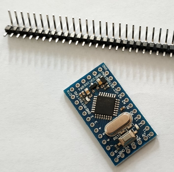
- Arduino Pro Mini 5v/16Mhz;
- Male, 40 x Pin header, 90 degrees angle, 2.54mm pitch;
- 8 ohm miniature speaker;
- 220 Ohm resistor;
- Support module for Arduino Pro Mini – STL file on Tinkercad;
- Wires.
I used an Arduino pro mini to process the signals from the reed switches and to control the RGB LEDs. At the same time, I thought that in order to enrich the experience of using this assembly, I should introduce the possibility to produce some sound effects. For this I used an 8 ohm speaker and a 220 ohm resistor. I put the Arduino module in a support printed on the 3D printer and I mounted all these parts in a box.
Step 5: The Enclosure
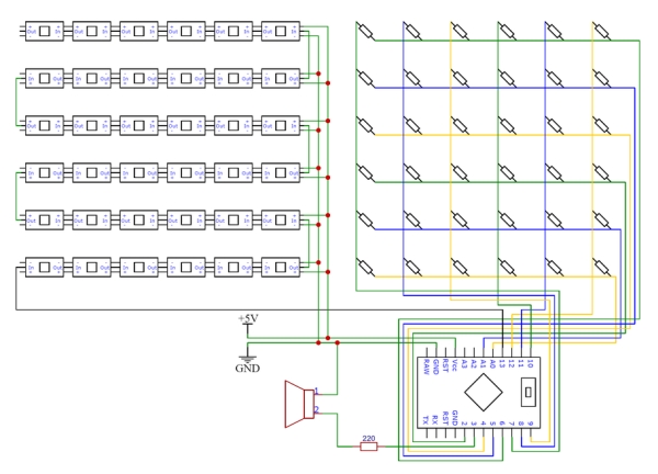
The schematic is above and the materials and components required are:
- 3D printed box – file on Tinkercad;
- 3mm thickness smoked plexiglass for display;
- Black semi transparent self-adhesive foil with frosted effect;
- 3mm thickness smoked plexiglass for bottom;
- 5.5×2.1mm DC connector female jack with cable;
- 5v/2A power supply.
After printing the box with the 3D printer and processing the bottom cover on the CNC I cut the smoked plexiglass to size and applied 3 layers of sticker with a frosted effect. I made all the soldering from Arduino to the reed switch matrix, led matrix, the speaker and power source as in the schematic. You can see in the photos above how I assembled everything. On the last photo you can see the USB to TTL module I used for programming the Arduino Pro Mini – more in this instructable Arduino Mini Unleashed – Arduino Mini for Begginers and in this very good article Arduino Pro Mini – How to upload code
I then went on to testing.
Step 6: Testing
In the intro I mentioned one of the great advantages of the Arduino platform, namely the large number of existing libraries. For this project I found two very well made and excellent libraries for my purpose.
The first one is the Keypad library Although the keypad library has the role of interfacing matrix keyboards with Arduino, it is very suitable for reading the status of reed contacts, in essence, it is also a kind of keyboard isn’t it? The advantage of this library is that it can read multiple, simultaneous contacts and no diodes are required for the reed switch matrix, because inactive rows and columns are placed in high impedance during scanning.
EDIT:Unfortunately, this is not true. With the reed contacts I couldn’t observe it but when I tried with an array of 12 touch buttons the ghosting effect was present. So for a correct reading of the status of the reed contacts a diode in series with each reed contact is needed. When I will build the next version of this magnetic board I will take this into account. Thanks to instructable member dnsbob for pointing me to this issue.
The second library is the FastLED library, I think everyone knows about this library, I have used it in many projects of mine, it is an excellent piece of software, it is worth trying to work with it.
So here is the video of the testing phase…
As you can see in the video, I tried magnetic balls of different sizes (5,6,8, and 10 mm in diameter). Do you notice how with the increase of the ball diameter, implicitly the intensity of the magnetic field, the number of reed contacts (number of lit LEDs) increases?
The keypad library allows the detection of multiple simultaneous switching on the reed contacts, which is why several LEDs light up around the magnetic ball. And when the ball has a stronger magnetic field, more LEDs light up. The maximum number of simultaneous contacts detected is 10, it can be changed in the keypad library file, I tried with LIST_MAX = 23 and it worked (look at the line “#define LIST_MAX 10 // Max number of keys on the active list.” in the Keypad.h file), that’s why you see more LEDs than 10 lit with the 10 mm ball. So in essence, in this variant the magnetic board is a display for the intensity of the magnetic field! 🙂 The test program source code is on Github.
Of course I did not stop here and, as I said, I will present three applications bellow that I think you will be interested in.
step 7: Applications
Magnetic Chase.
It is a simple game, in which the goal is to turn on the LEDs that light up one after the other on the display. But it would be best to watch the video below and you will see exactly what it is about.
I hope you liked it 🙂 The source code is here – Github.
Magnetic Paint
In this application I used the predefined color palettes from FastLED and the idea is to change the colors according to the palette depending on how long the reed switches contacts are closed. I think the video below is edifying.
The source code – Github.
Magnetic ToneMatrix
The last application is an attempt to transpose the ToneMatrix application on this magnetic board. Unfortunately the original link, which is in flash, no longer works, but you can find the javascript version here – https://www.maxlaumeister.com/tonematrix/. In principle, ToneMatrix is a sequencer based on the pentatonic scale that can produce very pleasant patterns. In my application, by moving the magnetic balls, the reed switches closes and the LEDs light up or, if they were previously lit, go out and sounds are played according to the current situation. The video below is an example of what I told you.
Note that the sounds in the column are not played simultaneously (as in the original version), they are played in arpeggios because the tone function can only play one sound at a time. Despite this, I think the sounds obtained are pleasant, aren’t they? 🙂
Step 8: Observations – Conclusions
Things can be taken well beyond that. I am thinking, for example, of using SMD reed contacts, these for example, they could make reed contact arrays suitable for 8×8 LED arrays like these. This could make larger magnetic boards, with more LEDs per unit that would allow much more attractive lighting effects.
I could also think of making a magnetic table on which some remote controlled cars are moving and they could only move on the surface where there are no LEDs of a certain color lit, that is something like the game TRON if you understand me 🙂 And more …
If you had the patience to follow me so far I think you will agree with me that the Arduino platform is amazing. From a reed switch and a LED I came to a sequencer. That’s pretty good, isn’t it? 🙂
I hope you liked my article and I look forward for your comments and (possible) criticisms 🙂