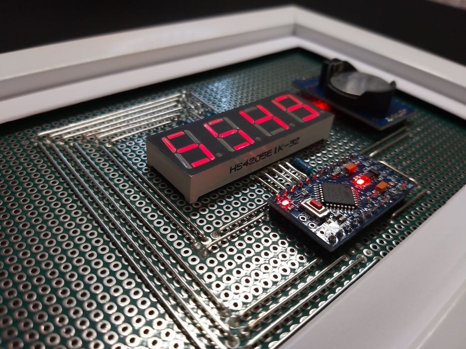
This unique clock reminds you to appreciate every single day, by displaying your current age in days (or weeks) on a seven segment display.
Step 1: You Will Need
Electronics:
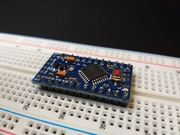
- Arduino Pro Mini 5V (or any other arduino with >= 12 GPIO Pins)
- 4 Digit 7 Segment Display
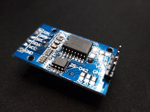
- DS3231 Real Time Clock Module
- 4x 200 Ohm Resistors
Materials:
- Picture Frame
- Perf Board (matching size)
- MicroUSB Breakout (or any other 5-12V power source)
- Wires/Hardwires
- Pin Headers (male, female)
Tools:
- Soldering Iron
- FTDI Programmer (in case of a pro mini)
Step 2: Prototyping
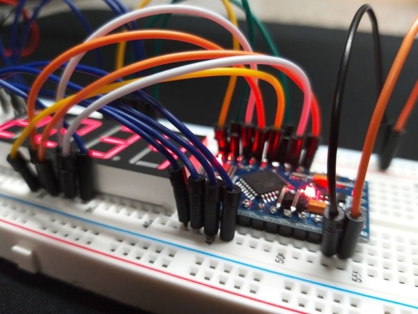
Before permanently assembling the components we need to check if everything works properly.
- Connect everything according to the schematic
- Check the COM-Port and install the latest drivers
- Compile and upload the provided sketch
Connections:
Common Cathode Display
- Pin 2 – COM4 (resistor)
- Pin 3 – g
- Pin 4 – c
- Pin 5 – DP
- Pin 6 – d
- Pin 7 – e
- Pin 8 – COM1 (resistor)
- Pin 9 – a
- Pin 10 – f
- Pin 11 – COM2 (resistor)
- Pin 12 – COM3 (resistor)
- Pin 13 – b
DS3231
- GND – GND
- 5V/VCC – VCC
- A4 – SDA
- A5 -SCL
If you are using a common anode display you need to make sure to adjust the pins on the breadboard or later on in the code.
Step 3: Modify the Parts
We need to modify some of our components, so that they fit inside the frame.
Arduino
- Solder on male pin headers (as shown)
- Add two wires to SDA and SCL
DS3231
- Desolder the 6 pinheaders
- Solder on 4 pin headers on the other side (as shown)
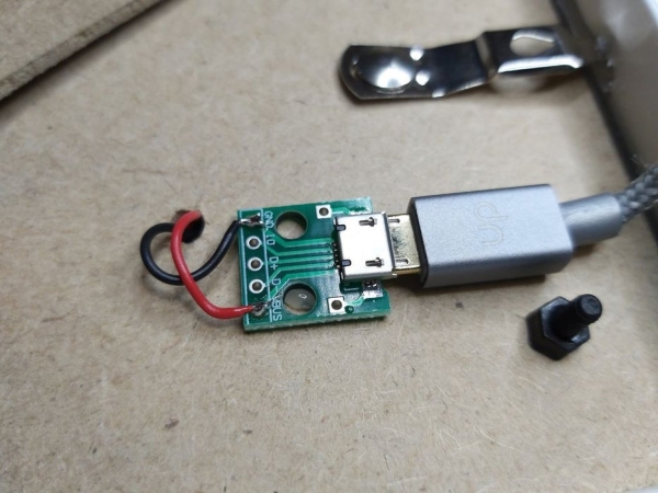
MicroUSB Breakout
- Solder on pin headers
Step 4: Building the Circuit Board
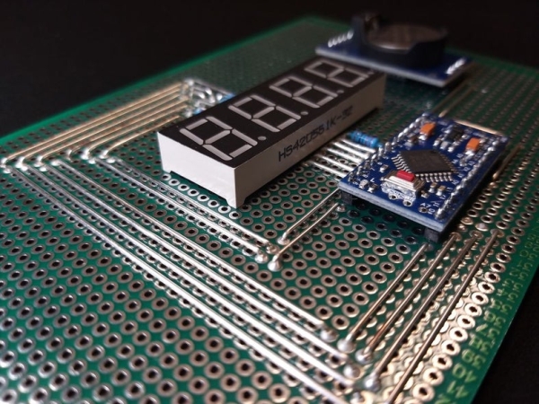
If everything worked flawlessly, you can start building the circuit board. The whole circuit board has to fit into the chosen picture frame. If your perf board has different dimensions you probably need to adjust the placement of the components.
1) Arrangement:
Position every component as shown in the schematic. If the diameter of your wires is >1mm you need to drill two holes to put the A4-SDA (grey) and A5-SDA (white) through it.
2) Attaching:
If every component is placed properly you can begin soldering on the components. Make sure to remove the remaining legs afterwards.
3) Wiring:
You can either use ordinary cables, by simply connecting them on the backside of the perf board, or silver wire on the front side. For doing so, you need to cut the silver wire to the matching length and bend its ends. Now you just have to place them accordingly and solder them on.
4) Check Connections:
If something does not work as it should or if you want be sure that you have connected everything correctly, you can check it using the continuity functionality of your multimeter.
Step 5: Modify the Picture Frame
- Drill 4 mounting holes and 1 hole for cables into the back plate of your frame
- Screw down the perf board (additionally with a few standoffs)
- Fix the microUSB breakout on the backside and connect it with the power cables (RAW, GND)
Depending on what you prefer, you can put the glass pane back in or use some kind of passepartout.
Step 6: The Code

Before uploading the code you need to make sure to install the necessary libraries and to define two parameters.
1) Your age in days (line 21) [https://www.calculator.net/age-calculator.html]
2) Additionally the time of your birth (line 23)
If the displayed value is wrong or needs to be changed, you have to clear the EEPROM!
Hopefully I could inspire you with that project. If you have any questions or improvements, please tell me.
Source: Arduino LifeClock