
Summary of Build An Arduino Laser Engraver
This article details the construction of a DIY Arduino-based laser engraver capable of engraving wood and cutting paper. The project integrates mechanical, electrical, and software components using NEMA 23 stepper motors, ballscrews for precise linear motion, and hollow aluminum posts for the frame. The author emphasizes safety regarding laser wavelengths and notes that while the machine is functional, it lacks fume extraction for plastics.
Parts used in the Arduino Laser Engraver:
- Arduino controller
- Laser diode module
- NEMA 23 stepper motors (qty: 2)
- Dedicated digital stepper drivers (qty: 2)
- 16mm ballscrews with C7 accuracy rating
- BK12/BF12 ballscrew supports
- 16mm hardened chromed shafts (500mm length, qty: 4)
- SC16LUU linear bearings (qty: 4)
- SK16 shaft supports (qty: 8)
- 50mm x 50mm hollow aluminum fence posts
- M5 socket head cap screws and nuts
- Aluminum angle brackets
- Motor couplers
- A4-sized clear acrylic sheets (4.5mm thick)
- Laser safety glasses
I started this project because I wanted to make something that had mechanical, electrical and software components. After looking around on Instructables, I figured that an Arduino based laser engraver would be an interesting machine to make, and that the machine itself could make interesting things. Laser diodes have also advanced quite a lot in the last few years, allowing reasonably powerful DIY laser engravers to be made without the hassles of laser tubes.
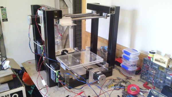
This machine can engrave wood and cut paper. I haven’t tried other materials yet because there is no fume extraction capability – plastics generally create toxic gases when burnt.
SAFETY WARNING – Please be safe when using lasers. The laser used in this machine can cause permanent eyesight damage, and probably even blindness. When working with powerful lasers (>5mW), always wear a pair of laser safety glasses designed to block your laser’s wavelength.
For a quick overview of the guts of the machine, have a look at the video below
(Note: The machine runs slightly faster now, and also has a different laser heatsink to the one in the video)
http://getburnt.weebly.com/gallery.html
A spreadsheet containing the parts list is below.
Also, for any Aussies unsure about the laser import laws, I’ve attached the current rules (at Dec 2013) below. Laser diodes and laser modules (such as the one in this machine) are legal, however laser pointers are prohibited.
This is a pdf version of the following webpage:http://www.customs.gov.au/site/page4372.asp
Step 1: Frame Design
Before starting construction, I made a CAD model of the machine to make sure that everything would fit, and to figure out the dimensions of the parts. Some screenshots of the machine’s CAD model are above.
The y-axis is on the bottom of the machine, and provides a moving base for the engraved piece. The x-axis is on the top, and moves the laser assembly (the laser isn’t shown in the model).
Step 2: Linear Motion Method
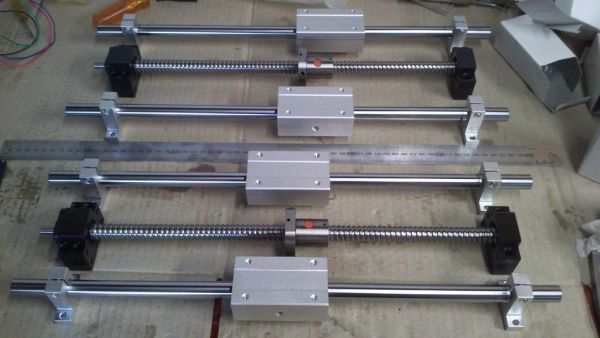
The machine uses ballscrews and linear bearings to control the position and motion of the X and Y axes.
The specifications of the machine’s ballscrews and accessories are:
16mm ballscrew, 400mm length (462mm including machined ends)
5mm pitch
C7 accuracy rating
BK12/BF12 ballscrew supports
I chose to use ballscrews due to their very high accuracy (minimal backlash), rigidity and efficiency. Since the ballscrew nut consists of ball bearings rolling in a track against the ballscrew, there is very little friction, which means the motors can run at higher speeds without stalling.
The second photo shows a test fitting for the x-axis. On either side of the ballscrew is a linear bearing on a steel shaft. This configuration is quite common for cnc machines, and provides a stable foundation for the base plate (Y-axis) and laser assembly (X-axis).
The parts I used are:
16mm hardened chromed shaft , 500mm length (qty: 4)
16mm linear bearing – SC16LUU (qty:4)
16mm shaft support – SK16 (qty:8)
The ballscrew nut’s rotational orientation is locked using a piece of aluminium(this is how we spell it in Australia!) angle attached to the moving component of the axis. This can be seen in the last photo, which shows the y-axis. The base plate is fastened to the two linear bearings, and to the ballscrew nut (through the aluminium angle). Rotation of the ballscrew shaft results in the linear motion of the base plate.
Step 3: Frame Construction
The ballscrew supports and shaft supports are mounted on 50mm x 50mm hollow aluminium posts. These posts are used for all major structural parts of the machine, and are actually aluminium fence posts (purchased at Bunnings, if anyone from Australia is reading). The thickness of the aluminium is about 2mm.
I chose to use these posts because they are easy to cut and drill, and also hold their shape well when supporting heavy loads. In addition, because they are square, they provide excellent reference surfaces to make sure things are parallel / perpendicular.
The holes were drilled using a cordless drill, and the posts were cut using a mitre saw. (It is also possible to cut the aluminium posts with a hacksaw).
M5 socket head cap screws, and M5 nuts were used to hold most of the parts together. I didn’t use a permanent fastening method because I wanted to keep everything adjustable. Using screws also means that the machine is easy to disassemble and modify for future upgrades.
Some pictures of the frame being built are above. The base of the Y-axis is made up of several A4-sized 4.5mm thick clear acrylic sheets.
Step 4: Stepper Motors + Drivers
After some poor results with NEMA 17 stepper motors in an earlier design, I decided to use some NEMA 23 motors with a decent torque rating for this machine. Strong stepper motors also require strong drivers to get the most out of them. As a result, I chose to use a dedicated stepper driver for each motor.
Some details about the chosen components are below:
Stepper Motor (qty:2)
NEMA 23 frame size
1.8Nm holding torque (255 oz-in)
200 steps / revolution (1.8 deg step angle)
Up to 3.0A current
Weight – 1.05kg (They are really heavy!!)
Bipolar 4 wire connection
Stepper Driver (qty:2)
Digital stepping driver
Microstepping feature
Output current 0.5A to 5.6A
Output current limiter (reduces risk of motors overheating)
Control Signals: Step and Direction inputs
Pulse Input freq up to 200kHz
20V-50V DC supply voltage
For each axis, the motor directly drives the ballscrew through a motor coupler. The motors are mounted to the frame using two aluminium angles and an aluminium plate. The aluminium angles and plate are 3mm thick, and are strong enough to support the 1kg motor without bending.
Note: It is really important to correctly align the motor shaft and ballscrew. The couplers I used have some flex to compensate for minor errors, but if the alignment error is too large, they will fail!
For more detail: Build An Arduino Laser Engraver
- What materials can this laser engraver process?
The machine can engrave wood and cut paper. - Can I use this machine to engrave plastics?
No, plastics create toxic gases when burnt and the machine lacks fume extraction. - Why did the author choose NEMA 23 motors over NEMA 17?
NEMA 23 motors were selected because they offer higher torque ratings and better performance than NEMA 17s. - How does the machine achieve high precision on the X and Y axes?
The machine uses ballscrews and linear bearings which provide minimal backlash, rigidity, and efficiency. - What type of structural posts were used for the frame?
The frame is constructed using 50mm by 50mm hollow aluminum posts, specifically aluminum fence posts. - Is permanent fastening used to assemble the machine parts?
No, M5 socket head cap screws and nuts are used so the machine remains adjustable and easy to disassemble. - What safety equipment is required when operating this laser?
Users must always wear laser safety glasses designed to block the specific wavelength of the laser. - Are laser diodes legal to import according to Australian rules mentioned?
Yes, laser diodes and modules are legal, though laser pointers are prohibited.